- SIGNA™ Hero 3.0T Service Methods
- 5852800-8EN Revision 1.0
- 00000018WIA30159230GYZ
- id_156670551.3
- Jul 5, 2019 5:47:15 PM
ICC Coolant Deionization
Prerequisites
| Required persons | Preliminary requirements | Procedure | Finalization |
|---|---|---|---|
| 1 | 5 minutes | 90-180 minutes, depending on initial resistivity value | 10 minutes |
| Item | Quantity | Effectivity | Part number | Manufacturer |
|---|---|---|---|---|
| Funnel | 1 | - | - | - |
| Water Removal Pump Kit | 1 | - | - | - |
| DVMR Deionization Kit | 1 | - |
5224090 | - |
| Deionization Filter Cartridge Kit | 1 | - |
5264701 | - |
| 5 gallon pail | 1 | - |
2239133 | - |
About this task
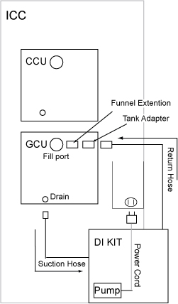
This procedure describes the process to deionize and filter the coolant for ICC cabinet. The Deionization Kit will hook-up to the cooling loop to increase the electrical resistivity level and to filter the coolant. Chemical additives will also be added back into each cooling loop. A general schematic of the setup for a cooling loop is shown below. Deionization can be performed while other planned maintenance tasks are being done in parallel since scanning is still allowed when the tool is hooked up and running.
Deionization and Filtering the Gradient Coil Coolant
Procedure
- Observe the suction line. Coolant should be trickling into the suction line. If coolant is observed in the suction line at the pump, the pump is sufficiently primed. If no coolant is observed in the suction line, verify that the return line is connected properly to the reservoir refill port. Note: DO NOT attempt to run the DI kit pump until the pump is primed.
Figure 2. GCU Setup 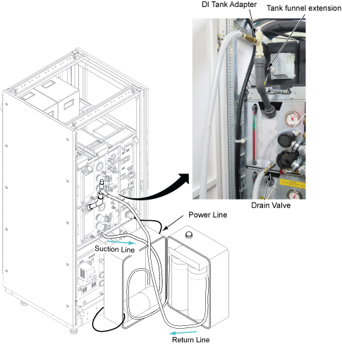
- Turn on the Service Outlet Breaker.
Figure 3. Service Outlet Breaker 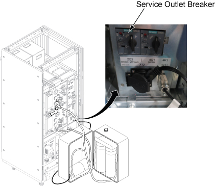
Notice Note: The deionization process for the Gradient Coil usually takes about 1 hour (but can take up to 3 hours, depending on the initial resistivity) and cannot be done while the system is in clinical scanning state. The process not only removes coolant contaminants but also coolant additives. Because of this, the procedure will run until the resistivity is > 600 kΩ-cm which could result in scan stop. Re-introducing the additives later will greatly decrease the coolant resistivity to the typical 7 kΩ cm to 12 kΩ cm level.Check the resistivity of Gradient Coolant from Functional Diag (). If resistivity is 600 kohm cm, turn off the Service Outlet Breaker.Error trip level and deionized resistivity value transfer table show as below:
Figure 4. Deionized Resistivity Transfer Table 
Figure 5. Functional Diag 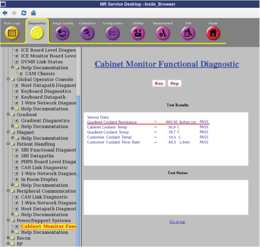 Note: If Gradient Coolant resistance is not within the specification but it does not change much, check that GCU is correctly working by checking the pressure meter.Note: If customer is scanning, exit the Common Service Desktop and perform [TPS reset] before turning over to the customer.
- Perform the following steps.
Figure 6. Remaining Coolant in DI Kit 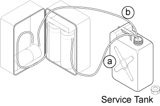
Fill the Gradient Coil Deionization Chemicals additive into GCU reservoir until the chemical reaches to the center of bottle label.Notice Figure 7. DI Chemical 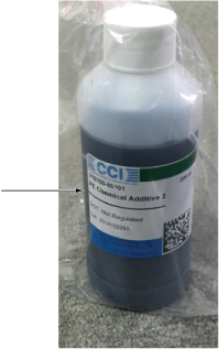 Note: If you are scanning:
If the chemical contents are filled into the reservoir too fast, the resistivity value may drop rapidly and reach a trip level, thus interrupting the customer scan. The resistivity should be in the 7kΩ-cm to 12kΩ-cm range after adding the GC additives.
Note: Dispose of the Deionization Chemicals per local regulation.
Deionization and Filtering the Power Electronics Coolant
Procedure
- Connect the DI Kit coolant return hose quick disconnect to the DI tank adapter.
Figure 8. PE Setup 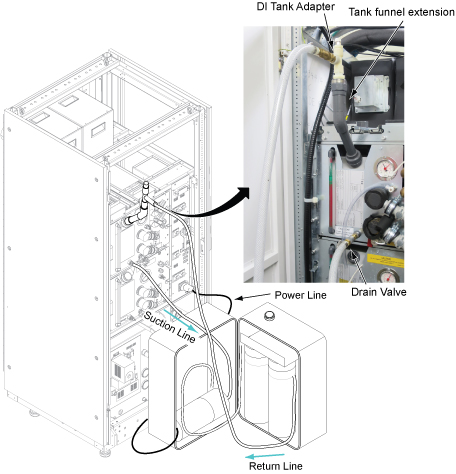
- Perform the following steps.
Figure 9. Remaining Coolant in DI Kit 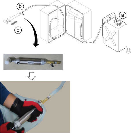
CAUTION
Fill the Power Electronics Deionization Chemicals additive into CCU reservoir until the chemical reaches the center of bottle label.Notice Figure 10. DI Chemical Note: Dispose of the Deionization Chemicals per local regulation.
DI Kit Filter Replacement
Procedure
- Unplug the DI Kit power cord and extension cord.
- Using the wrench tool, do the following:
Finalization
Procedure
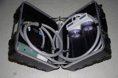
- Coil the DI Kit hoses using the Velcro straps. Close the case and clasps.
Figure 11. Packing the DI Kit