- Discovery MR750w and SIGNA™ Architect T 3.0T System Service Methods
- 5690002-2EN Revision 4
- 00000018WIA30F1BE20GYZ
- id_131067163.0
- Aug 29, 2019 1:44:05 AM
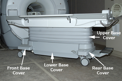
Patient table upper bellows and lower base side cover removal
Prerequisites
| Personnel requirements | |||
|---|---|---|---|
| Required persons | Preliminary requirements | Procedure | Finalization |
| 1 | - | 5 minutes (each) | - |
| Tools and test equipment | |||
|---|---|---|---|
| Item | Quantity | Part number | Manufacturer |
| Non-magnetic Service Tools | 1 |
5112581 | - |
About this task
The Upper Bellows, an accordion style cover, can be positioned up or down depending on the type of servicing needed. The Lower Base Side Cover is a solid single cover that runs the length of the lower chassis from the front caster assembly to the rear caster assembly on each side.
To fasten the upper bellows
Procedure
- Remove four screws (two at front, two at rear) that connects the bottom end of the Upper Bellows to the top of the Lower Base Side Cover.
Figure 1. Upper bellows screws 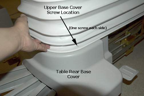
To remove the lower base side cover
Procedure
- On the left or right side of the table, remove two screws from the lower base side cover.
Figure 2. Lower base side cover screws 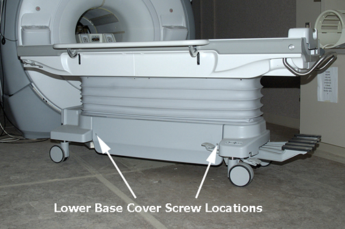
- Lift the lower base side cover off of front and rear guide studs on the front and rear base covers.
Figure 3. Front and rear base covers