
- Discovery MR750w and SIGNA™ Architect T 3.0T System Service Methods
- 5690002-2EN Revision 4
- 00000018WIA3004C030GYZ
- id_123749381.6
- Jan 17, 2020 11:32:44 AM
3.0T MNS Cabinet Component Replacements
Prerequisites
| Required persons | Preliminary requirements | Procedure | Finalization |
|---|---|---|---|
| 1-4 | Not Applicable | 10-45 min. (see Procedure Overview) | Not Applicable |
| Item | Quantity | Effectivity | Part number | Manufacturer |
|---|---|---|---|---|
| Phillips Screwdriver | 1 | - | - | - |
| 5/16 inch Wrench | 1 | - | - | - |
| 8 mm Wrench | 1 | - | - | - |
| Cut-Resistant Protective Gloves | 1 | - | - | - |
| Item | Quantity | Effectivity | Part number | Manufacturer |
|---|---|---|---|---|
| RF Controller Module | 1 | - |
2206456-24 | - |
| Driver Module | 1 | - | - | - |
| RF Power Amplifier Module | 1 | - |
2206456-3 | - |
| RF Amplifier Combiner Coupler | 1 | - |
2206456-4 | - |
| RF Power Supply | 1 | - |
2206456-8 | - |
| 5 Amp, 250 V Fuse | 1 | - |
46-170021P29 | - |
| ||||||||||||
| Condition | Reference | Effectivity | ||||
|---|---|---|---|---|---|---|
|
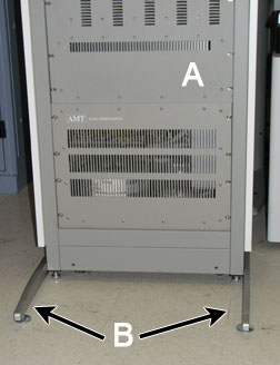
Install anti-tip legs on both sides of the MNS cabinet.
The anti-tip legs are strapped inside the rear of the cabinet on the
left side. Remove the anti-tip legs from the cabinet, and align them
with the screw openings at the bottom of the cabinet. Screw on leg
on each side.
| - | - |
About this task
Overview
This document outlines how to replace the FRUs for the 8 kW MNS cabinet: AMT system control module, driver module, power amplifier module, combiner, power supply, and fuses. The table below details each component's personnel requirements and procedure timing.
| FRU | Persons Required | Procedure Timing |
| AMT System Control Module | 1 | 30 min. |
| Driver Module | 1 | 30 min. |
| Power Amplifier Module | 1 | 30 min. |
| Combiner | 1 | 30 min. |
| Power Supply | 4 | 45 min. |
| Fuses | 1 | 10 min. |
-
Introduction to MNS Cabinet – Introduction to MNS Cabinet: This section displays the FRU locations for MNS components from the front and rear sides of the MNS cabinet.
-
Replacing AMT System Control Module – Replacing AMT System Control Module
-
Replacing Driver Module– Replacing Driver Module
-
Replacing Power Amplifier Module(s)– Replacing Power Amplifier Module(s)
-
Replacing Combiner– Replacing Combiner
-
Replacing Power Supply– Replacing Power Supply
-
Replacing Fuses– Replacing Fuses
Introduction to MNS Cabinet
About this task
This section displays the location of MNS FRUs in the MNS cabinet from a front and rear view.
Procedure
- MNS cabinet front view of FRU components.
Figure 2. MNS Cabinet Front View 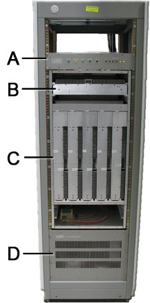
A AMT control module B Driver module (pre-driver) C Power amplifier modules D Power supply - MNS cabinet rear view of FRU components.
Figure 3. MNS Cabinet Rear View 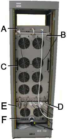
A AMT control module B Driver module (pre-driver), located behind fan plate C Power amplifier modules, located behind fan plate D Combiner, located behind fan plate E Power supply F Fuses
Replacing AMT System Control Module
About this task
Procedure
- Disconnect the system power cable at J12 on the power supply.
Figure 4. AMT System Control Module - Cabinet Connections 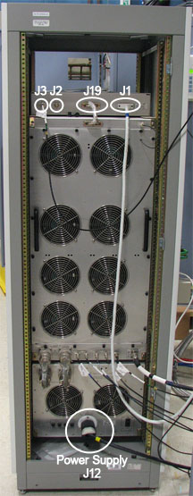
- Working from the front of the system control module, carefully
remove the four large mounting screws that attach the module to the
rack. Set the screws aside in a safe place.
Figure 5. AMT Location in MNS Cabinet 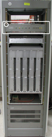
Replacing Driver Module
About this task
Procedure
- Working from the front of the rack, carefully remove the two
mounting screws that attach the driver module to the rack. The screws
are located below the driver module air intake vents. Set the screws
aside in a safe place.
Figure 6. Driver Module Mounting Screws 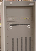
- Disconnect the fan AC power cable at J17 at the rear of the cabinet.
Figure 7. MNS Cabinet - AC Power Cable 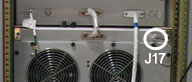
- Use a 5/16 inch wrench to remove the RF cable at J25.
Figure 8. RF Cables on Driver Module 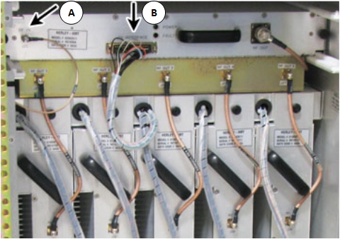
A J26 INTERFACE B J25 RF IN - Carefully remove the RF output cables 1 through 5 from J27-1 through J27-5 on the driver
module.
Figure 9. RF Output Cables 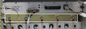
- Loosen the two thumbscrews that attach the driver module to
the rack.
Figure 10. Driver Module - Rack Thumbscrew 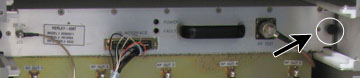
Replacing Power Amplifier Module(s)
About this task
Procedure
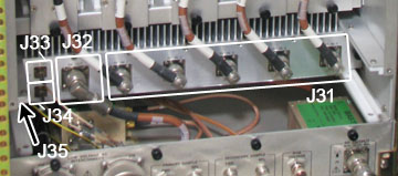
- Disconnect all the power amplifier interface cables at connectors J29-A through J29-E; or, for an
individual module replacement, disconnect only that module's connectors.
Figure 11. RF Cables for Power Amplifier 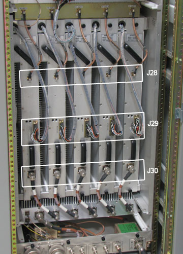
- Disconnect the RF input cables at J28-A through J28-E; or, for an individual module
replacement, disconnect only that module's cables with a 5/16 inch
wrench.
Figure 12. Removing RF Input Cables 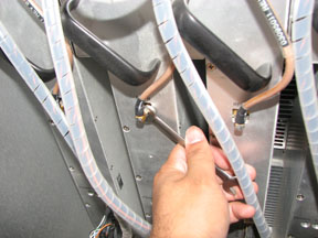
- Working from the front of the rack, remove the two corresponding
screws that attach the power amplifier module to the front panel.
The screws are located next to the air intake vents. Keep the screws.
Figure 13. MNS Cabinet Front Screws Location 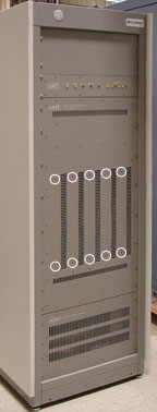
- Working from the rear of the rack, carefully slide the power
amplifier module out of the rack.
Figure 14. Removing the Power Amplifier Module 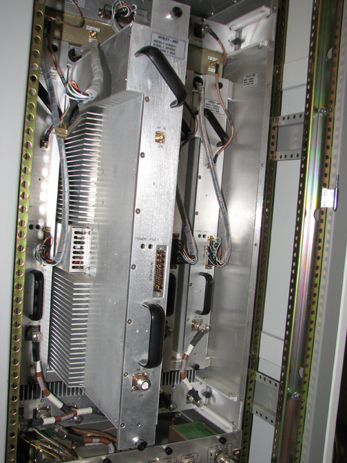
Replacing Combiner
Replacing Power Supply
About this task
Procedure
Install anti-tip legs on both sides of the MNS cabinet Figure 1. The anti-tip legs are strapped inside the rear of the cabinet on the left side. Remove the anti-tip legs from the cabinet, and align them with the screw openings at the bottom of the cabinet. Screw one leg onto each side.CAUTION 
- Disconnect the system power cable at J12 on the power supply.
Figure 16. MNS Power Supply Connections 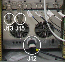
- Remove the two screws that attach the power supply to the rack.
The screws are located in the lower left and right corners of the
power supply. Keep the screws.
Figure 17. Removing Screws 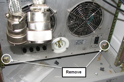
- On the front of the MNS cabinet, remove the eight large screws
that attach the power supply to the rack. Set the screws aside in
a safe place.
Figure 18. Location of Screws to Remove 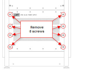
Working from the front, with the help of three additional field engineers, carefully slide the power supply out of the front of the rack.Warning Figure 19. Power Supply Partially Removed 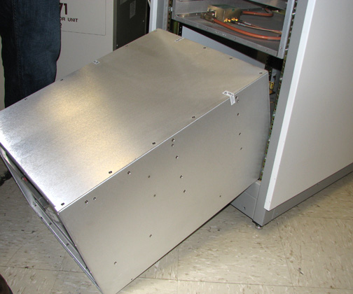 Note:
Note:It may be easier to partially remove the power supply before setting it on the floor, as shown above.
Replacing Fuses
About this task
The fan module and the internal power supply are equipped with replaceable fuses. The fans are equipped with two 250 volt, 8 amp, time-delay type 8AT fuses. The internal power supply is equipped with two 250 volt, 5 amp, time-delay type 5AT fuses. Refer to Figure 3 for details.
Finalization
Finalization
If you performed a replacement from Replacing AMT System Control Module, Replacing Driver Module, Replacing Power Amplifier Module(s), or Replacing Combiner, perform the 8kW 3.0T MNS Amplifier Calibration.