
- Discovery MR750w and SIGNA™ Architect T 3.0T System Service Methods
- 5690002-2EN Revision 4
- 00000018WIA3018C030GYZ
- id_123734321.9
- Dec 20, 2019 9:16:35 AM
Body Coil Restoration after XRMw Replacement
Prerequisites
| Required persons | Preliminary requirements | Procedure | Finalization |
|---|---|---|---|
| 1 | Not Applicable | Not Applicable | Not Applicable |
| ||||
Procedure
- Restore front body coil mounting brackets to the original location.
Figure 1. Restore mounting brackets 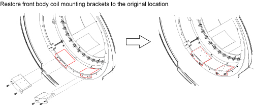
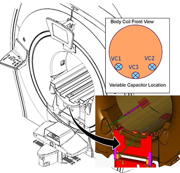
Restore Body Coil. Refer to RF Body Coil Replacement.Notice - Perform Body Coil Tuning and record fS11 and fS22. Try to tune
Body Coil by referring to Body Coil Tuning Procedure.
If VC1 or VC2 reached the end of the rotation, follow the instruction below per recorded fS11 and fS22 values.
-
128.15MHz ≤ fS11 or fS22 ≤ 128.4MHz: Increase dielectric material by one step.
Figure 2. Increase dielectric material by one step 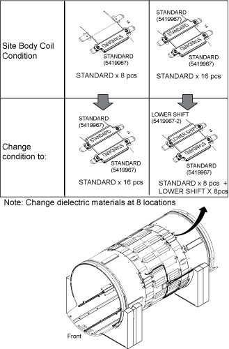
-
128.45MHz ≤ fS11 or fS22: Increase dielectric material by two steps.
Figure 3. Increase dielectric material by two steps 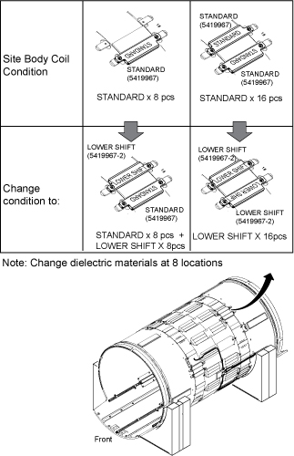
-
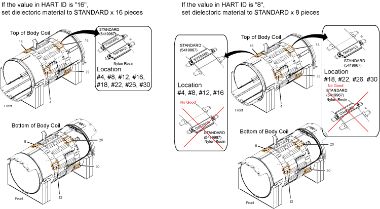
127.4MHz ≤ fS11 or fS22 ≤ 127.65MHz: Decrease dielectric material by one step.
Figure 4. Decrease dielectric material by one step 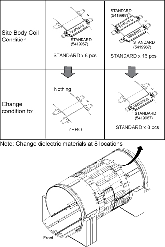
-
fS11 or fS22 ≤ 127.4MHz: Decrease dielectric material by two steps.
Figure 5. Decrease dielectric material by two steps 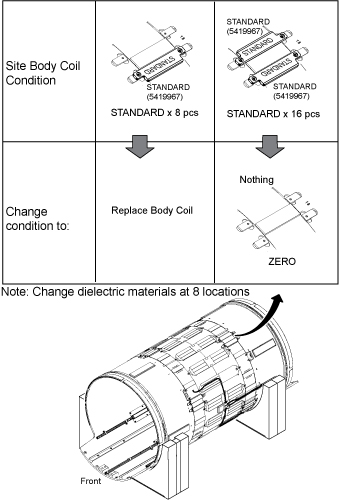 Note:
Note:When replacing dielectric material to “Standard x 8 pieces” or “Standard x 8 pieces + Lower Shift x8 pieces”, the order is important. Follow the illustration below.
Figure 6. Dielectric Material Order 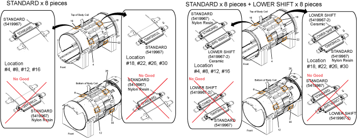
-
Finalization
No finalization steps.