
- Discovery MR750w and SIGNA™ Architect T 3.0T System Service Methods
- 5690002-2EN Revision 4
- 00000018WIA307EBE20GYZ
- id_131065303.9
- Feb 4, 2021 7:51:05 PM
Body Coil Tuning (Network Analyzer Kit 5336593-3 or Later)
Prerequisites
| Required persons | Preliminary requirements | Procedure | Finalization |
|---|---|---|---|
| Not Applicable | Not Applicable | Not Applicable |
| Item | Quantity | Effectivity | Part number | Manufacturer |
|---|---|---|---|---|
| Network Analyzer Service Tool Kit | 1 | - |
5336593-3 or 5336593-4 | - |
| Body Loader with Sphere Phantom | 1 | - |
2371511 | - |
| ||||||||||||
| Condition | Reference | Effectivity |
|---|---|---|
|
Body Coil Centering must be done. | - | - |
|
Cradle is not located in the magnet bore. | - | - |
|
Bridge is installed in magnet bore. | - | - |
|
Phantom is set-up correctly (System Pre-setup for Tuning). | - | - |
|
Cables are connected correctly (Tuning Cable Connection (Equipment Setup)). | - | - |
|
Driver module DD Bias is in Body Mode (-13.6 VDC unloaded, ~2.6 VDC loaded; exact voltages are not critical). | - | - |
|
Body Coil Temperature matches magnet room temperature (HEC air flow — ON) for a minimum of 15 minutes. | - | - |
About this task
This procedure is for network analyzer kit 5336593-3 or later.
Body coil tuning is performed by adjusting variable capacitors (VC1, VC2, VC3) to tune f1, f2, f3, and MagS21 according to the network analyzer screen. If it is difficult to adjust parameters by variable capacitors, replacement of dielectric material might be required (also according to the network analyzer screen).
| STEP | PROCEDURE | SECTION |
| 1 | Start | |
| 2 | System Pre-setup for Tuning | System Pre-setup for Tuning |
| 3 | Calibration of Network Analyzer | Calibration of Network Analyzer |
| 4 | Tuning Cable Connection (Equipment Setup) | Tuning Cable Connection (Equipment Setup) |
| 5 | Perform Body Coil Tuning per Network Analyzer Navigation | Body Coil Tuning using Network Analyzer Navigation, Further Adjustment, Troubleshooting |
| 6 | Finalization | Step 1 |
System Pre-setup for Tuning
Procedure
- Note: The following process must be used to tune the coil to specification. However, if the current tuning values of a particular coil are wanted, the original macro can be utilized. The original macro is found in Body Coil Tuning (Network Analyzer Kit 5336593-2).Perform the following sub-steps to prepare a body coil scan on the scan window to set up driver module body bias mode.
- On the exciter/ref clock module located in the PEN cabinet,
set the RF Enb switch to down (Disable).
Figure 1. Exciter/Ref Clock Module 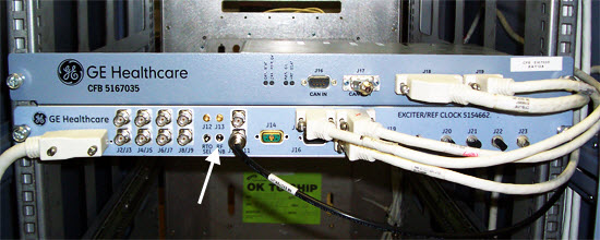
- On the exciter/ref clock module located in the PEN cabinet,
set the RF Enb switch to down (Disable).
- Remove the bridge cover, right center cover, and right rear
cover.
Figure 2. Remove Covers 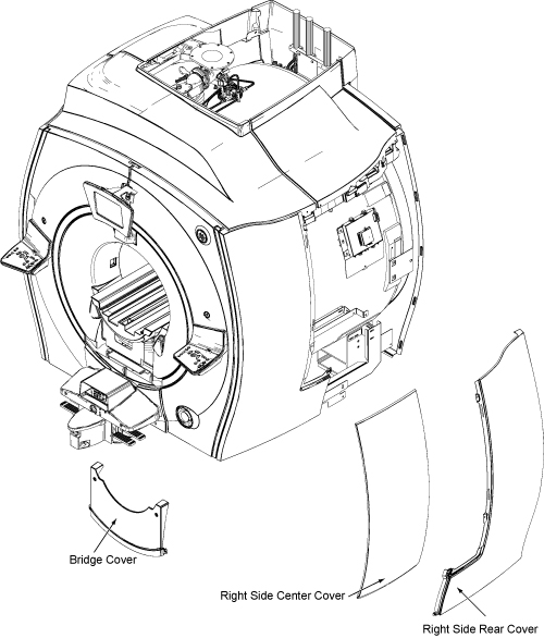
- Place body loader with phantom on the bridge and push it to
the magnet center so that the front edge of body loader is 835 mm
(33 inches) away from the front edge of the bridge. The loader and
phantom assembly will sit on the belt path notch and are centered
left-to-right on the bridge.
Figure 3. Body Loader Setup 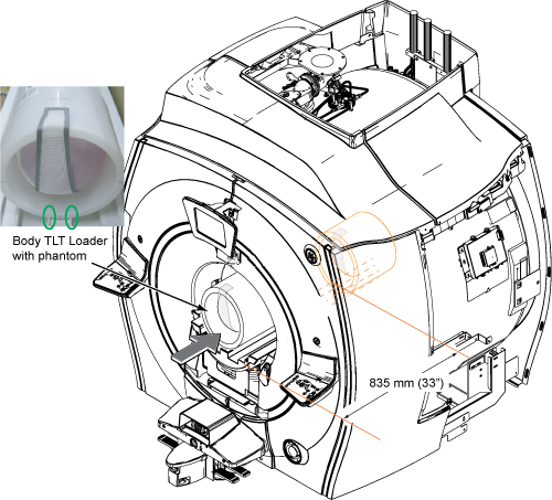
Calibration of Network Analyzer
Procedure
Connect the bias T at Port 1 and Port 2. Do not connect the bias cable at this time.CAUTION 
Figure 4. Bias T installation 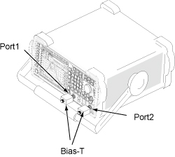
Notice Note:Power ON the network analyzer. If no power is seen, confirm that the AC power switch on the rear of the unit is in the 'I' position.It is recommended that you connect a mouse to one of the USB ports on the network analyzer.
If not using the mouse, use the hard keys. For example, select the Menu hardkey and then use the arrow <> hardkeys to navigate and highlight, and the ENTER hardkey to select from menu.
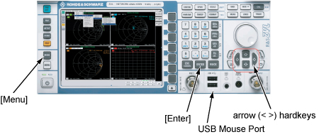
Figure 5. Power ON 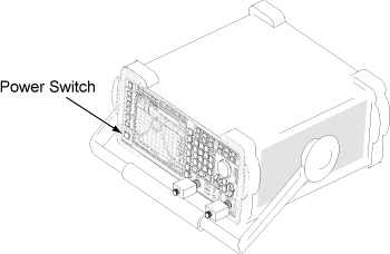
- If the network analyzer is not ready, start either the ZVL Analyzer (5336593-3) from the Windows screen, or the Vector Network Analyzer (5336593-4). (This step might not be needed.)
Figure 6. Start ZVL Analyzer (5336593-3) 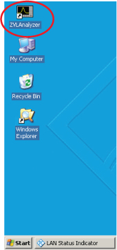
Figure 7. Start Vector Network Analyzer (5336593-4) 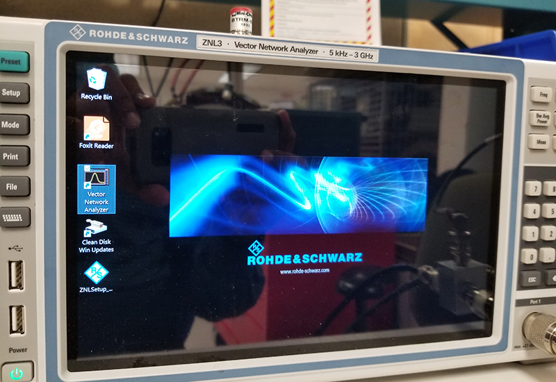
- For Vector Network Analyzer (5336593-4), do the following to change the Preset mode to Network Analyzer:
- Close the window.
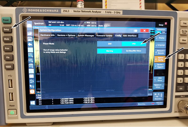
- Close the window.
- Select 750w body coil tuning, based on network analyzer:
Option Description For ZVL Analyzer (5336593-3) Select . Figure 8. 750w Body Coil Tuning.lnk 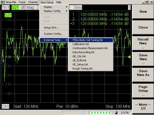
For Vector Network Analyzer (5336593-4) Select the Start menu, and then select 750w Body Coil Service Tuning. Figure 9. 750w Body Coil Service Tuning 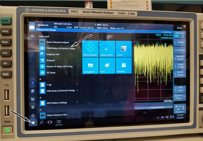
- The following screen displays. For button selection, proceed to Step 7.
Figure 10. Calibration Start Menu 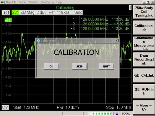
- Select the correct button as follows:
- If calibration of network analyzer has been done using the same macro, click Skip to skip the calibration and go to equipment setup.
-
If Skip is clicked, the confirmation screen shown in Figure 11 displays. Confirm the condition again and click OK. Then, go to Tuning Cable Connection (Equipment Setup).
Figure 11. Confirmation Screen 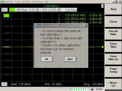
-
If any condition is not satisfied, click Quit, then press blue Pre-Set hardkey button on the front left of unit, and start the tool again.
-
- If calibration of network analyzer has been done using the same macro, click Skip to skip the calibration and go to equipment setup.
- When OK is selected at Step 7, the following message displays. Confirm that the DC cable is not connected to bias T and click OK.
Figure 12. Message 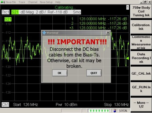
- Connect N(m) to N(m) coaxial cable to bias T of Port 1.
Figure 13. Cable Connection 1 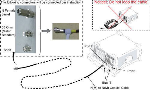 Note:
Note:Do not touch cable ends, and minimize human interaction during network analyzer calibration, because this can change the impedance of the calibration setup.
Also it is best to not cross the cables, and route them so that they are parallel and separated from each other as much as possible.
Note: It is recommended that the 50 ohm load (Match Standard) be measured with a DVM to confirm that it is operational (50 ohms +/- 5 ohms). Connecting it to the end of BNC-f to BNC-f adapter or BNC-f to N-m adapter and measuring through opposite end of adapter sometimes provides the most reliable electrical connection for measurement. - Connect N female barrel and “BNC female to N male” to the end port 1 of the channel 1 cable. Do not attach any BNC standard connectors. Click OK when the following message is displayed. Do not make any changes until prompted.
Figure 14. N Female Barrel and Male N to BNC Female 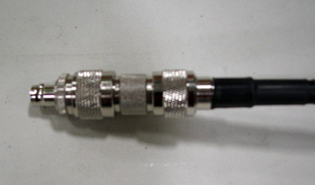
Figure 15. Message for Open 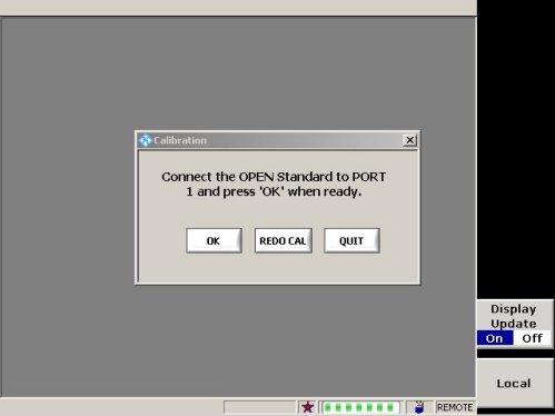 Note: It will take about 15 seconds to display next message after clicking OK.
 - Connect Short standard to “BNC female to N male” and click OK when the following message is displayed.
Figure 16. Message for Short 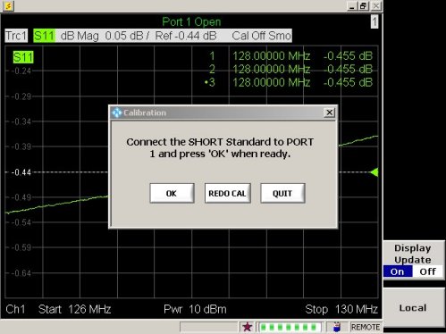
- Remove Short, connect 50 Ohm load standard and click OK when the following message is displayed.
Figure 17. Message for Match Standard (50 Ohm Load) 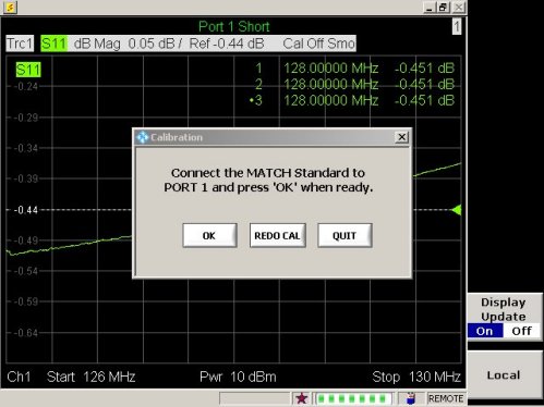
- Connect port 1 and port 2 cables through female barrel.
Figure 18. Cable Connection 2 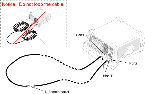
- Click OK when the following message is displayed. Calibration is complete.
Figure 19. Message for Through Standard 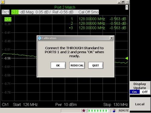
- After calibration is complete, the following screen displays. Proceed to Tuning Cable Connection (Equipment Setup). Keep the network analyzer screen as it is.
Figure 20. Message for Equipment Setup 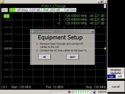
Tuning Cable Connection (Equipment Setup)
Procedure
Remove cables from the DTRS switch for J2, J7, J8, and J3.Warning 
Figure 21. Tuning Cable Connection 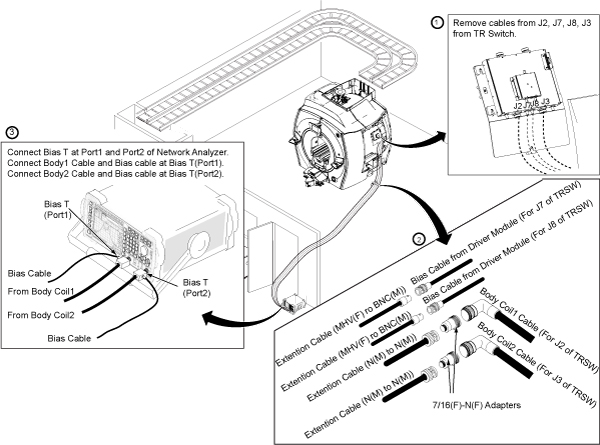
Body Coil Tuning using Network Analyzer Navigation
Procedure
- Note: Before performing this procedure, all Required Conditions must be met.After the tuning cable connection (equipment setup) is completed, click OK.
Figure 22. Message for Equipment Setup - Ch1 measurement will start. Click OK to
record f1.
Figure 23. Message for Ch1 Measurement 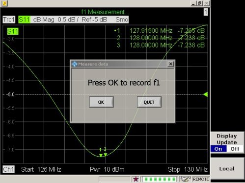 Note:
Note:If the following screen displays, it means S11 magnitude is unusual.
Figure 24. Message for Unusual S11 Magnitude 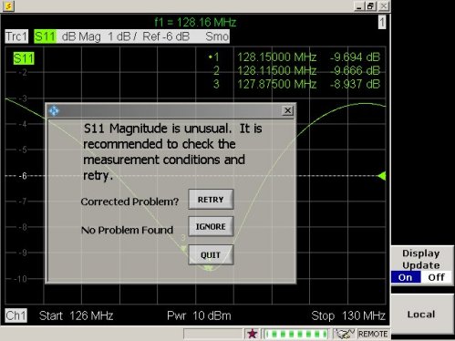
In this case, check the following conditions:
-
Cradle is not located in magnet bore.
-
Bridge is installed in magnet.
-
Phantom is set up correctly as described in System Pre-setup for Tuning.
-
Cables are connected correctly as described in Tuning Cable Connection (Equipment Setup).
-
Driver module DD bias in body mode (-13.6 VDC unloaded, ~2.6 VDC loaded; exact voltages are not critical).
Notice
After the problem is corrected, click Retry.
-
- Ch2 measurement will start. Click OK to
record f2.
Figure 25. Message for Ch2 Measurement 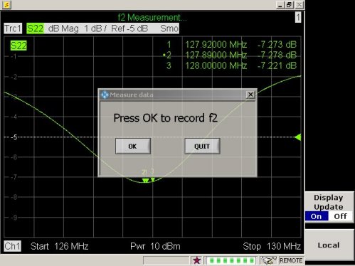 Note:
Note:If the following screen displays, it means the S22 magnitude is unusual.
Figure 26. Message for Unusual S22 Magnitude 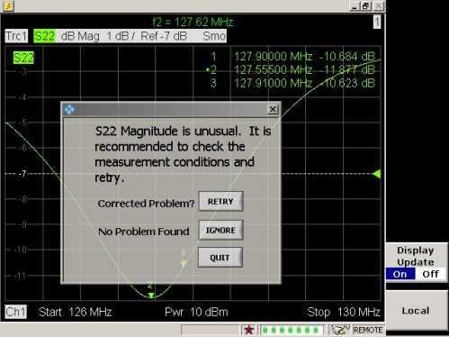
In this case, check the following conditions:
-
Cradle is not located in magnet bore.
-
Bridge is installed in magnet.
-
Phantom is set up correctly as described in System Pre-setup for Tuning.
-
Cables are connected correctly as described in Tuning Cable Connection (Equipment Setup).
-
Driver module DD bias in body mode (-13.6 VDC unloaded, ~2.6 VDC loaded; exact voltages are not critical).
Notice
After the problem is corrected, click Retry.
-
- From this point on, the display of the network analyzer will
guide the operation. Follow the instructions shown.Note:
If the body coil is within specification, a pop-up (shown in Figure 34) displays, which means you are done tuning.
If VC1 CW or VC1 CCW is shown, turn VC1 using stick to tune f1 until VC1 TUNED! is displayed. After VC1 TUNED! is displayed, click OK to go to the next step.
Figure 27. Tuning VC1, VC2 or VC3 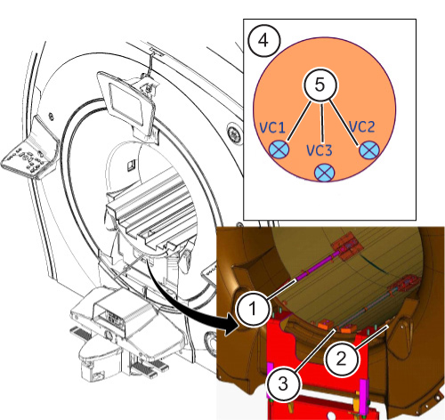
ITEM DESCRIPTION 1 VC1 location 2 VC2 Location 3 VC3 location 4 Body coil front view 5 Variable capacitor location Note: The macro will dictate which capacitor should be tuned first, second, then third.Figure 28. VC1 Display 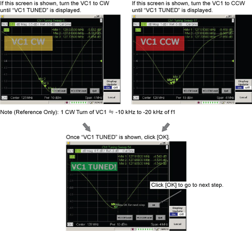 Note:
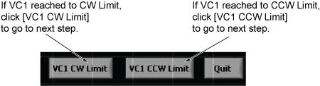
Note:If VC1 reached the CW or CCW limit, click the appropriate button to go to the next step.
-
If VC2 CW or VC2 CCW is shown, turn VC2 using stick to tune f2 until VC2 TUNED! is displayed. After VC2 TUNED! is displayed, click OK to go to the next step.
Figure 29. VC2 Display 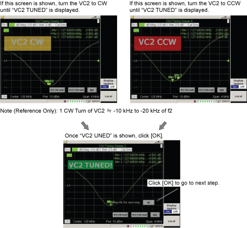 Note:
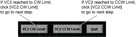
Note:If VC2 reached the CW or CCW limit, click the appropriate button to go to the next step.
-
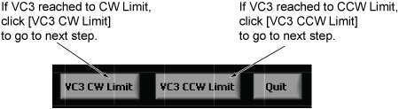
If VC3 CW or VC3 CCW is shown, turn VC3 using stick to tune f3 until VC3 TUNED! is displayed. After VC3 TUNED! is displayed, click OK to go to the next step.
Figure 30. VC3 Display 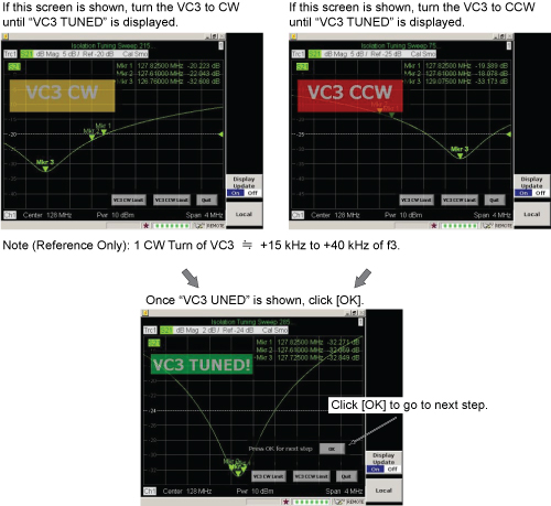 Note:
Note:If VC3 reached the CW or CCW limit, click the appropriate button to go to the next step.
 Note:
Note:If the following screen displays, it means S11, S22, or S21 magnitude is unusual.
Figure 31. Message for Unusual S11, S22, or S21 Magnitude 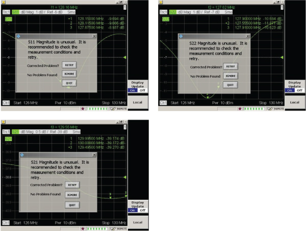
In this case, check the following conditions:
-
Cradle is not located in magnet bore.
-
Bridge is installed in magnet.
-
Phantom is set up correctly as described in System Pre-setup for Tuning.
-
Cables are connected correctly as described in Tuning Cable Connection (Equipment Setup).
-
Driver module DD bias in body mode (-13.6 VDC unloaded, ~2.6 VDC loaded; exact voltages are not critical).
Notice
After the problem is corrected, click Retry.
-
-
If the following screen is displayed, do not edit or continue procedure until the coil is removed. It will be necessary to remove the coil, determine the dielectric material configuration, and change the dielectric material before proceding. Go to Further Adjustment.
Notice
Figure 32. Message for Dielectric Material Adjustment 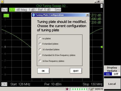
-
- When the following screen displays, click OK to start the calculation.
Figure 33. Record Data Screen 
- Measured data is calculated and the result is shown on the display.
Proceed as described below.
- Note:When the screen below is displayed, body coil tuning is completed. Go to Step 1.
The measured data is archived in the following directory of network analyzer:
-
C:\Program\750w Body Coil Tuning Macro
-
File name example: September 19, 2012 @ 5_35 PM Data.txt
-
Select Firmware Exit, My Computer to save to USB memory stick.
Notice
Figure 34. Measured Data (All Pass) 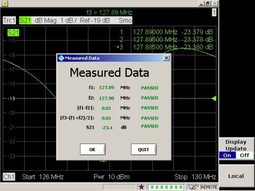
-
- If any of the results fail, the screen below displays. Click OK and follow the navigation screen to perform more tuning.
Figure 35. Measured Data (Failed) 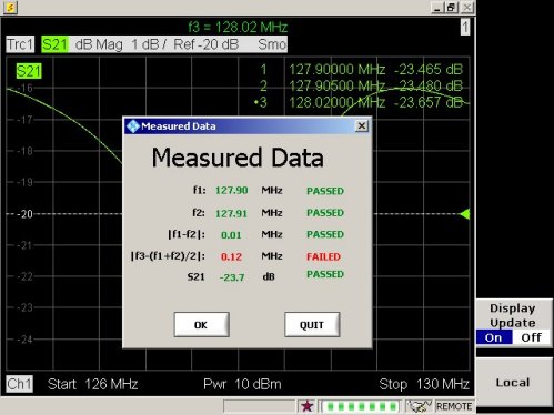
Further Adjustment
About this task
This procedure is required if the following screen displays.
Procedure
- Check the site’s body coil condition.
Figure 37. Dielectric Material Configuration Check 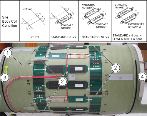
ITEM DESCRIPTION 1 Body coil removed 2 Dielectric material 3 Rear or service end 4 Front or patient end Note: If there is no body coil FRU case available, place the body coil on two pads, making sure to protect the drive cables of the body coil from damage. Make sure the body coil does not roll over. - From the menu, select the option corresponding to the site configuration
and click OK.
Figure 38. Select from Menu 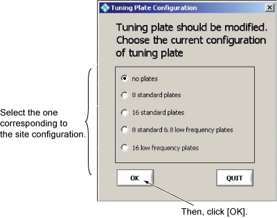
- Change dielectric material according to the message.
Figure 39. Change Dielectric Material 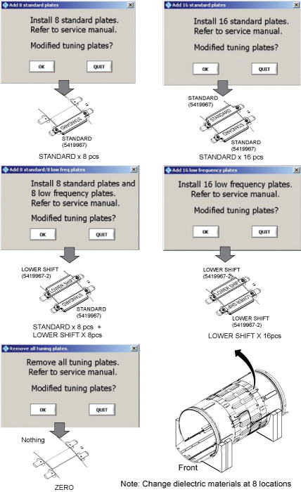 Note: The body coil FRU includes dielectric materials for adjustment, so no kit needs to be ordered. If dielectric material is required after XRMw replacement, order Dielectric Material FRU Kit (5423650).Note:
When replacing dielectric material to Standard x 8 pieces or Standard x 8 pieces + Lower Shift x8 pieces, the order is important. Follow the illustration below.
Figure 40. Dielectric Material Order 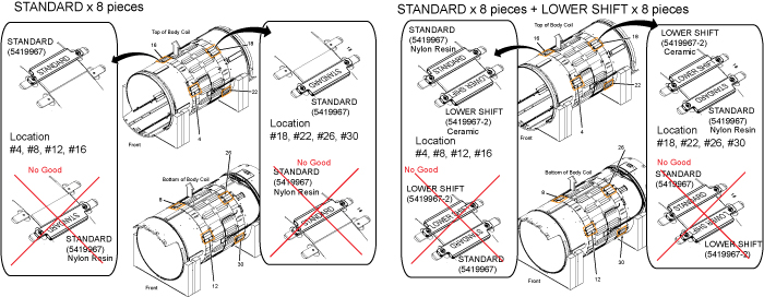
After changing the dielectric material, install the body coil by reversing the removal. See RF Body Coil Replacement.Notice
Troubleshooting
Procedure
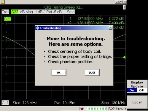
-
Perform Body Coil Centering.
-
Confirm bridge alignment and height are correct as described in the installation manual.
-
Check phantom position.
-
Replace the body coil.
Finalization
Procedure
- On the exciter/ref clock module in the PEN cabinet, set the
RF Enb switch to up (Enable).
Figure 42. Exciter/Ref Clock Module