Discovery MR750w and SIGNA™ Architect T 3.0T System Service Methods
5690002-2EN
Revision
4
Object ID: 00000018WIA30EC4E20GYZ
Topic ID: id_13106424 Version: 3.6
Date: Nov 12, 2020 3:48:46 PM
RF body coil replacement
Prerequisites
Table 1. Personnel requirements
Required persons
Preliminary requirements
Procedure
Finalization
3
Not Applicable
4 hours
-
Table 2. Tools and test equipment
Item
Quantity
Effectivity
Part number
Manufacturer
Safety Glasses
1
-
-
-
Cut-Resistant Gloves
1
-
-
-
Safety Shoes
1
-
-
-
Small Carpenter
Level
1
-
-
-
Authorized Personnel
Floor Sign
1
-
2289812
-
Nonmagnetic Titanium Service Tool Kit, Large Set
1
-
5112581
-
Step Gauge (stored
at front mounting bracket of magnet)
1
-
5397937
-
Table 3. Consumables
Item
Quantity
Effectivity
Part number
Manufacturer
Adhesive
1
-
46-220312P1
-
Anti-seize
1
-
2119594
-
Table 4. Replacement parts
Item
Quantity
Effectivity
Part number
Manufacturer
Discovery MR750w
3.0T Body Coil and FRU Case (includes dielectric materials used during
replacement)
1
-
See FRU Manual
-
Table 5. Safety
DANGER
Strong Magnetic Field!
Ferrous materials can become dangerous projectiles in the
presence of the magnetic field Produced by the Magnet.
Do not Bring any ferromagnetic tools or equipment into
the magnet room.
CAUTION
Dangerous work area!
Use of heavy equipment for coil removal and replacement
presents hazards to all personnel in the area.
Set up restricted barriers and signs limiting access to the work area.
Notify all affected personnel in the area prior to starting the service activity. Review safety procedures and restricted areas for the job.
CAUTION
Potential injury!
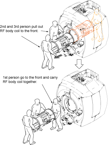
The body coil is heavy.
The body coil weighs approximately 95 lb (45 kg) and requires
three people in order to replace.
About this task
Use this procedure to replace the RF body coil.
Procedure
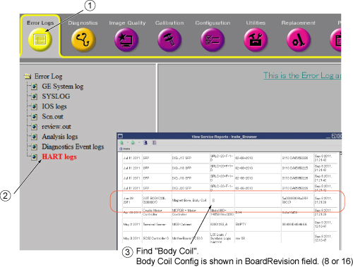
Locate HART log information as shown in items ① and ② below.
In item ③ select View Current Status, find the BoardRevision column, scroll down and find 3T
BODYCOIL, and on the same row and fourth column from left,
record HART ID value of 8 or 16.
Figure 1. HART ID information
HART ID value (8 or 16)
Perform LOTO on the PGR cabinet. See the MR Service
Safety Manual, PN 5452735.
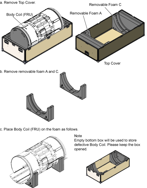
Outside the magnet room, open the FRU box and unpack the FRU
body coil.
Figure 2. FRU body coil unpacking
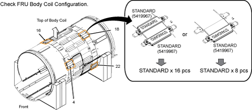
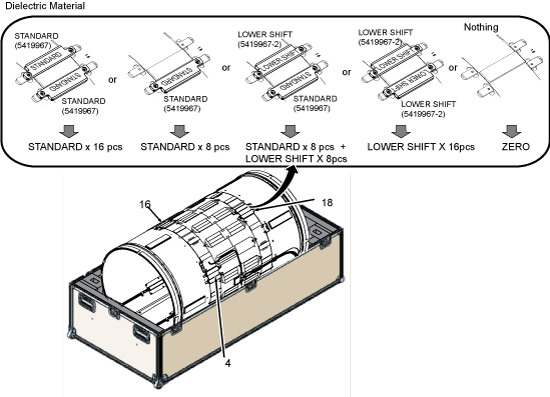
Check the configuration of dielectric material for the FRU body
coil.
Figure 3. Dielectric material for FRU body coil
Table 6. Record dielectric material configuration (FRU body coil)
Configuration of dielectric material (FRU body coil)
Note: Dielectric materials are stored in the FRU box. If additional dielectric material is needed, the Dielectric Tuning FRU Kit is PN 5423650.
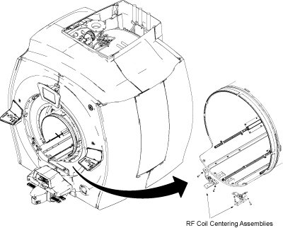
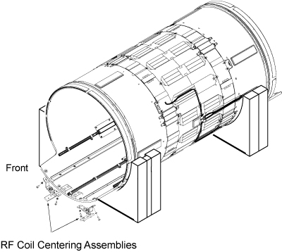
Transfer the front RF coil centering assemblies (front) which
were used for the defective RF body coil to the new RF body coil.
Figure 12. Transfer front RF coil centering assemblies
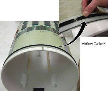
Inspect the airflow gaskets (5404530 and 5404530-2). Gaskets must be securely bonded along the entire length.
Notice: Before each body coil installation, inspect the airflow gaskets (5404530 and 5404530-2). Gaskets must be securely bonded along the entire length.
Figure 13. Airflow Gaskets
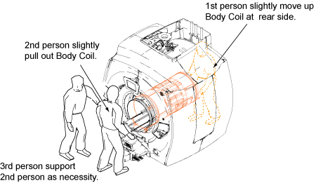
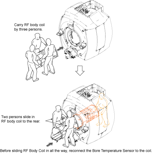
Slide in the new RF body coil.
Figure 14. Slide in RF body coil
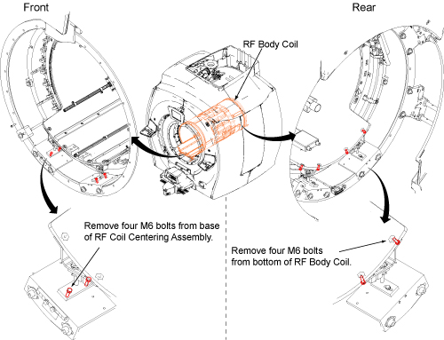
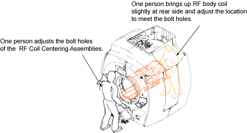
Attach the RF body coil using bolts and washers in reverse order
of removal.
Figure 15. Restore RF Body Coil
Notice
The MR750w body coil configuration has changed. There were modifications to the body coil which required changes to the RF cables that run between the body coil and the DTRSW. Make sure that the proper cables are installed during body coil replacement. Failure to install proper cables will result in early failure of the DTRSW.
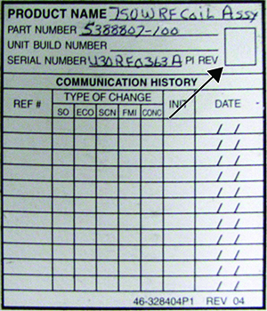
Coil Revision Number Location
Note the revision number of the Replacement RF coil.
If revision number is 5 or greater, confirm part numbers of
cables between RF body coil and DTRSW are 5746690 and 5746690-2. If
the existing cables have part numbers different from these, locate
new RF cables included with the body coil FRU and install between
body coil and DTRSW.
If the revision number of the Replacement RF coil is 4 or lower,
use existing cables and do not replace with those included with body
coil FRU.
Notice: Do not skip the RF body coil isolation procedure. It has a great influence on body coil tuning.
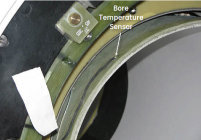
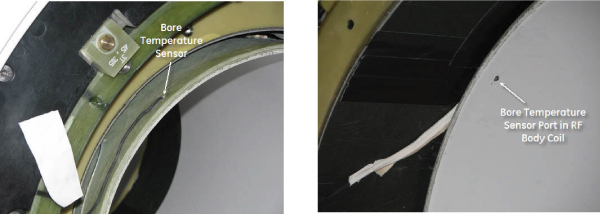
Reconnect the bore temperature sensor to the coil.
Figure 16. Bore temperature sensor
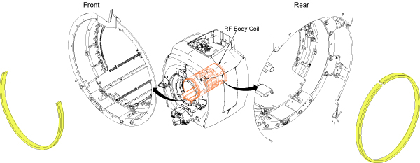
Install the yellow foam as previously installed (front: 2/3
of the diameter with the top 1/3 open; rear: full diameter around
body coil).
Figure 17. Yellow foam
Replace the front end bell. See Front End Bell Removal and Installation. Confirm
the gap between the front end bell and the RF body coil is 2.5 +/-
0.5 mm with a desired gap of 2.0 mm.
Replace the rear end bell. See Rear End Bell Removal and Installation. Confirm
the gap between the rear end bell and the RF body coil is 2.5 +/-
0.5 mm with a desired gap of 2.0 mm.
Reconnect the two air hoses at the rear end of the body coil.
Reconnect the two RF transmit cables and the HART ID cable to
the RF body coil.