
- Discovery MR750w and SIGNA™ Architect T 3.0T System Service Methods
- 5690002-2EN Revision 4
- 00000018WIA3029EE20GYZ
- id_131065313.4
- Jan 28, 2020 1:21:59 PM
Bridge alignment
Overview
This procedure describes how to align the bridge. Proper bridge alignment is critical to image quality and reliability of the table components.
Personnel requirements
| Required persons | Preliminary requirements | Procedure | Finalization |
|---|---|---|---|
| 1 | Not Applicable | 3 hours | Not Applicable |
| Item | Quantity | Effectivity | Part number | Manufacturer |
|---|---|---|---|---|
| Nonmagnetic Titanium Service Tool Kit, Large Set | 1 | - | 5112581 | - |
| Bridge Height Gauge or non-ferrous measuring device | 1 | 5346292 (gauge packaged with MR450w/750w dock assembly) | ||
| Non-Ferrous Level | 1 |
Safety
| DANGER | |
|---|---|
Preparing system for bridge alignment
- If necessary, remove the front bridge cover.
- Loosen the four nuts attaching the bridge to the rear pedestal. The bridge must be free from the rear pedestal during the Z-direction alignment.
Loosen the bolts on the rear pedestal attaching it to the magnet bracket.
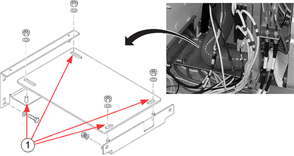
| Item | Description |
| 1 | 4 nuts holding rear pedestal bracket |
Z-Direction bridge alignment
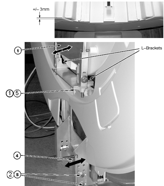
These steps provide instructions to align the bridge in the Z-direction (in/out of the magnet bore) until the front surface of the bridge aligns with the leading edge of the front bridge cover to within ±3 mm.
-
To align the bridge to the front bridge cover, push or pull the bridge with the support upper bracket attached. Loosen the four bolts (M10) under the lower bracket in the front, and the nuts attaching the bridge to the rear pedestal. This movement allows the L-brackets to slide toward or away from the magnet. Confirm that the bridge is free from the rear pedestal.
- If there is insufficient room to make the adjustment, loosen the four bolts (two on each side) holding the support lower bracket to the bridge support magnet mount assembly.
- Align the bridge.
- Move the support lower bracket until the ±3.0 mm bridge-to-front-bridge-cover alignment has been achieved.
- Retighten bolts on the front bracket and on the rear pedestal.
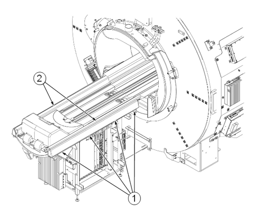
X-Direction bridge alignment
These steps provide instructions to align the bridge in the X-direction (left to right of the magnet bore) until the edge of the bridge aligns with the front bridge cover.
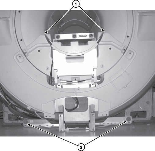
- Align the bridge in the X-direction (left/right in the magnet bore) by shifting the entire front bridge support assembly until the distance between the bridge and RF body coil is equal on both sides of the bridge. It may be necessary to loosen the two M10 bolts that fasten the bridge support assembly to the magnet feet. Notice: The bridge must not be in contact with the RF body coil along its entire length.
- After adjustment is complete, tighten the two M10 bolts that fasten the bridge support assembly to the magnet feet.
- Check that the bridge support upper assembly is not in contact with the front end bell, and the support lower bracket is not touching the floor. This is to ensure that there is no vibration “short circuit.”
Y-Direction bridge alignment (front of magnet)
These steps provide instruction to use the bridge height gauge to align the bridge in the Y-direction (up/down in the magnet bore) to attain 582 mm - 585 mm between the top of the patient bore and the bridge surface.
- Make sure that the lower bridge support does not touch the magnet room floor (2 mm minimum clearance).
Figure 4. Maintain Spacing from Floor 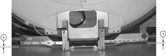
- Align the bridge in the Y-direction (up/down in the magnet bore) to within 582 mm - 585 mm using the bridge height gauge at the front of the magnet.
Figure 5. Y-Direction alignment 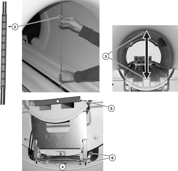
- Make sure the distance measured is between the top of the RF body coil and the bridge surface under the belt.
- Adjust the M10 nylon nuts at the bottom of the bridge support upper bracket to raise and lower the bridge to attain the 582 mm - 585 mm distance between the top surface of the RF body coil and the surface under the belt on the bridge.
- Use a level to make sure the bridge is level in the X-direction. (The bubble on the level should be between the lines). Adjust M10 nylon nuts as necessary.
- Tighten the two M10 bolts and the M10 nylon hex nuts on each side.
Rear split bridge height adjustment (rear of magnet)
See Y-Direction bridge alignment (front of magnet) for the correct distance between the bridge and the top of the RF coil.
The bridge does not need to be “level” to earth in the Z-direction to align the bridge surfaces. A level is not required at this point of the installation, just a straight edge (you can use a level as a straight edge.)
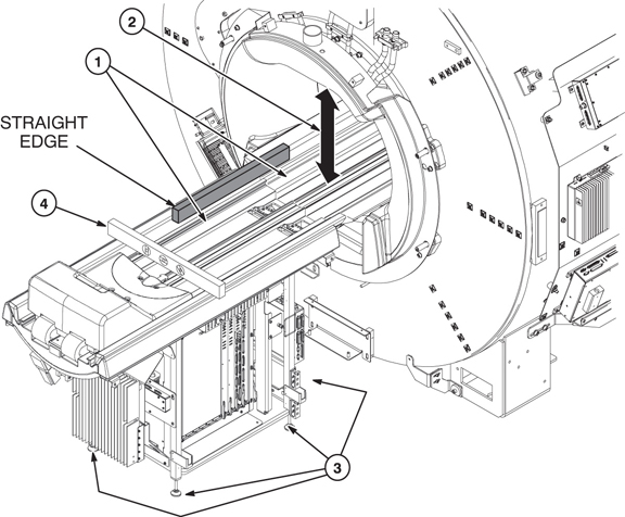
- If the bolts holding the two bridges were loosened for the Z-direction alignment, tighten them. Use a straight edge to make sure that the front and rear bridge surfaces, on both sides of the bridge where the LPCA wheels roll, are even. This provides smooth travel for the carriage wheels. If they are uneven, refer to the next step.
- Align the bridge in the Y-direction (up/down in the magnet bore) to within 582 mm - 585 mm using the bridge height gauge (delivered to site packaged with dock assembly) at the rear of the magnet.
- Adjust the rear pedestal feet (by turning) to raise and lower the bridge to attain the 582 mm - 585 mm distance between the top of the patient bore and the surface under the belt on the bridge.
- At this point in adjusting the rear pedestal, use a level to make sure the bridge on the rear pedestal is level in the X-direction. Make sure to use a level that is short enough to avoid resting on the rear bumpers. Adjust rear pedestal feet as necessary.
Front and rear split bridge alignment adjustment
- Adjust the left and right rear pedestal bumpers by loosening the four fasteners under each bumper.
- Move each bumper until a uniform gap is made. The gap between the rear split bridge and left and right rear pedestal bumpers should be uniform along the entire length.
- Tighten the fasteners underneath each bumper.
Finalization
- Tighten all fastener connections on bridge and rear pedestal after adjustment is complete.
- Confirm all fasteners on the lower bracket between the magnet and the rear pedestal are tightened.
- If the front cover was removed, reinstall it.
- If this procedure was done after installation and calibration, run Dual drive quadrature tool for any isocenter calibration changes.