- Discovery MR750w and SIGNA™ Architect T 3.0T System Service Methods
- 5690002-2EN Revision 4
- 00000018WIA30941E20GYZ
- id_131064509.1
- Oct 11, 2021 6:20:13 PM
8 kW 3.0T MNS amplifier calibration
Prerequisites
| Personnel requirements | |||
|---|---|---|---|
| Required persons | Preliminary requirements | Procedure | Finalization |
| 1 | - | 120 minutes | - |
| Tools and test equipment | |||
|---|---|---|---|
| Item | Quantity | Part number | Manufacturer |
| Flathead Screwdriver, at least 2 inches long | 1 | - | - |
| RF Power Measurement Kit (use one of the listed) | 1 | Kit PN 5307511-2 (Bird wattmeter) orKit PN 5307511-3 (Bird wattmeter) | - |
| Digital Multimeter (DMM) | 1 | - | - |
| 3.0T 31P T/R Switch (available on site with customer) | 1 |
2354050 (non-RoHS) 5409918 (RoHS) | - |
| Safety | ||||
|---|---|---|---|---|
| ||||
| ||||
| ||||
About this task
Follow this procedure after MNS Installation and Upgrade (3.0T) to calibrate either the CPC or AMT/Herley 8 kW amplifier for 3.0T.
The 8 kW AMT/Herley amplifier is the original amplifier and is easily identified by cables connecting to the rear of cabinet.
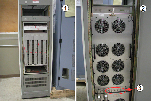
| Item | Description |
| 1 | Front of 8 kW AMT/Herley cabinet |
| 2 | Back of 8 kW AMT/Herley cabinet |
| 3 | Cable connections |
The CPC MNS amplifier is a new amplifier. Cables connect to the top of the cabinet for the CPC MNS amplifier. There are now two versions of the CPC MNS amplifier.
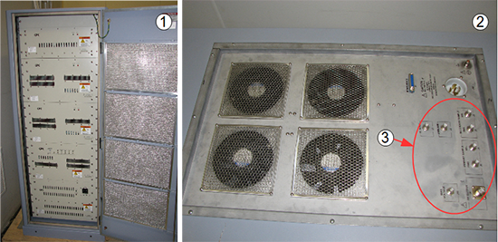
| Item | Description |
| 1 | Front of CPC cabinet |
| 2 | Top of CPC cabinet |
| 3 | Cable connections |
Calibration setup
System Setup
Procedure
- On the front of the driver module, set the T/R switch to Disable. This disables the T/R
fault reporting.Note: Leave HV and DD set to Enable.
Figure 3. Driver module switch 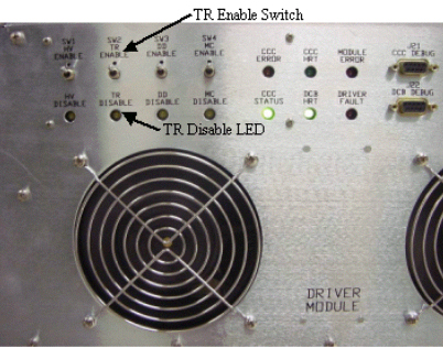
- Move the RF Enable S2 switch on the MNS
exciter to the DISABLE (down) position.
Figure 4. RF enable switch on exciter 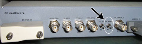
AMT/Herley amplifier setup
Procedure
- With the covers removed, notice the two holes for gross (6.0 dB) and fine (0.5 dB) attenuation adjustments as pictured in Figure 5 and Figure 6.Note: It is possible that these two holes are covered with an external screw. If so, remove the screw so that the amplifier looks like the one in Figure 5.
Figure 5. AMT/Herley amplifier with covers removed 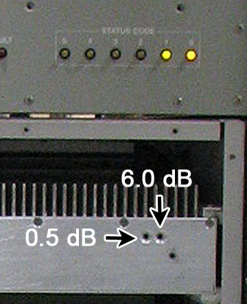
Indicators point to adjustment points.
Figure 6. AMT/Herley amplifier detail of dB adjustment 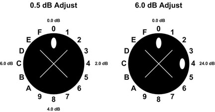
Bird Wattmeter setup
Procedure
- Disconnect the MNS output cable.
- (For AMT/Herley amplifier) Disconnect J4 from the RF amplifier.
- (For the original CPC amplifier, part number 5411744) Open the rear door and disconnect J3 from the combiner module at the top of the cabinet.
- (For the new CPC amplifier, part number 5750811) Open the rear door and disconnect J2 from the power amplifier at the bottom of the cabinet.
Figure 7. Coupler attached to J3 on combiner 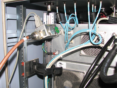
Figure 8. Coupler attached to J2 on power amplifier 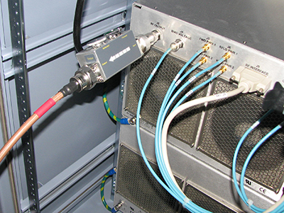
- Set up the wattmeter as shown below.
- (For AMT/Herley amplifier) Connect the input of the coupler to J4 (output connector).
- (For the original CPC amplifier, part number 5411744) Connect the input of the coupler to J3 (output connector). Do not connect the coupler at the top of the MNS cabinet as the cable may not reach the dummy load.
- (For the new CPC amplifier, part number 5750811) Connect the input of the coupler to J2 (output connector). Do not connect the coupler at the bottom of the MNS cabinet as the cable may not reach the dummy load.
Figure 9. Wattmeter setup – bird wattmeters 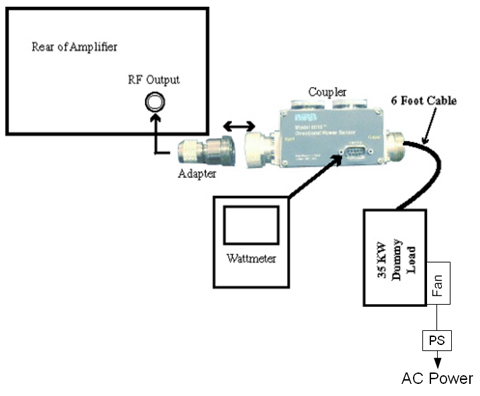
- Lock the elements into place using the locking tab on each sensor.
Figure 10. RF coupler setup 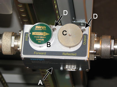
A
Wattmeter sensor
B
Forward sensor element
C
Blank slug
D
Sensor locking tabs
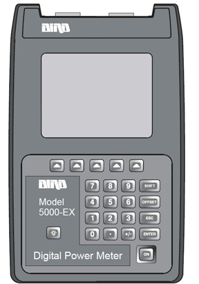
Setting up Bird 5000-EX wattmeter to measure forward MNS maximum power
About this task
Procedure
- Verify that the output reads 43, and then press ENTER.
Figure 12. Wattmeter display set to read 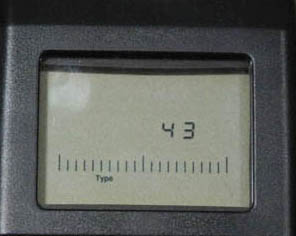
- All kits require an offset to make sure of accurate measurement. Locate the Element Offset Factors card in the kit.
(For single drive RF amplifiers) Find the offset for 3T G3 or DVMR Body Output.
(For MNS amplifiers) Find the offset for 3T MNS 8kW Output.
Figure 13. Example element offset factors card 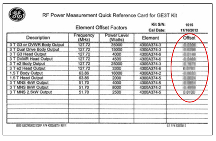
- Press OFFSET on the wattmeter. Enter the numerical value from the offset card and press Enter.Note: To enter a negative value, first enter the numerical value, then the minus symbol (–).
Figure 14. Wattmeter set to display peak power 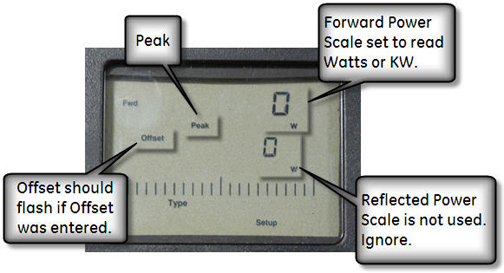
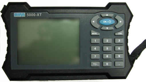
Setting up Bird 5000-XT Wattmeter to measure forward MNS maximum power
About this task
Procedure
- Verify that the output reads 43, and then
press OK.
Figure 16. Wattmeter set to read 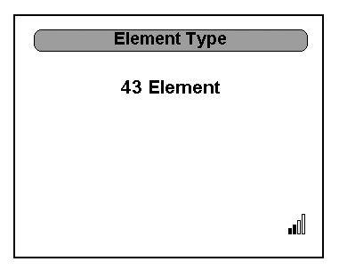
- All kits require an offset to make sure of accurate measurement. Locate the Element Offset Factors card in the kit.
Find the offset for “3T MNS 8kW Output.”
Figure 17. Example element offset factors card - Press ◄ to return to measurement mode.
Figure 18. Wattmeter set to display peak power 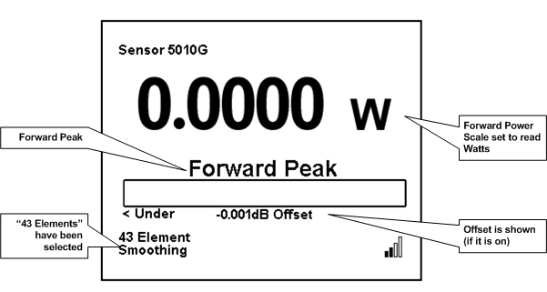
Calibrate MNS amplifier
About this task
Procedure
- Connect the MNS 31P T/R switch to the LPCA.
Figure 19. MNS 31P TR switch connection to LPCA 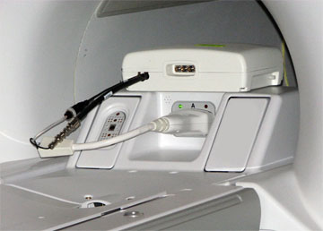
- Start the RF/UPM tool:
Figure 20. UPM tool interface 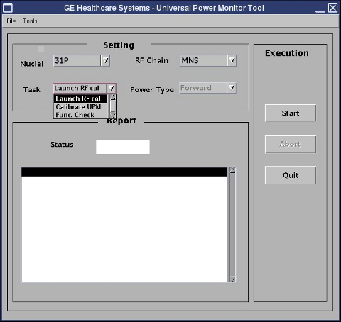
- Configure the UPM tool as follows:
- Click the Patient icon to go to the Scan workplace.
Figure 21. Patient icon 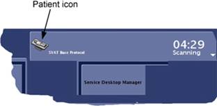
- Click the Patient icon to go to the Scan workplace.
For AMT/Herley amplifier
Procedure
For CPC amplifier
Procedure
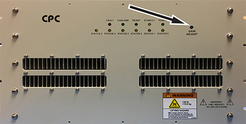
- Adjust for proper RF output by either toggling the switches
on the original amplifier, or by adjusting the potentiometer on the
new amplifier.
Figure 22. Control switches on CPC amplifier 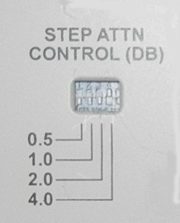
Figure 23. Potentiometer on CPC amplifier