
- Discovery MR750w and SIGNA™ Architect T 3.0T System Service Methods
- 5690002-2EN Revision 4
- 00000018WIA3085CE20GYZ
- id_131063953.3
- Oct 11, 2021 6:13:21 PM
B0 Drift Calibration
Prerequisites
| Required persons | Preliminary requirements | Procedure | Finalization |
|---|---|---|---|
| 1 | - | 4 to 12 hours | - |
| Item | Quantity | Effectivity | Part number | Manufacturer |
|---|---|---|---|---|
| Body TLT Phantom and Sphere | 1 | - |
2360037 | - |
| Service Filler Panel | 2 | Curved table |
5344577 | - |
| Condition | Reference | Effectivity |
|---|---|---|
|
All other applicable calibrations must be complete. | - | - |
About this task
Unwanted changes in the main magnetic field strength can occur when the spatially uniform field component is altered for a short term, during the process of scanning, or when the spatially uniform field component is permanently altered. This is known as short-term B0 drift. All MR systems that use passive shimming have B0 drift. However, the MR750w system has a much higher drift (up to 150 Hz per hour) because it uses a 3.0T magnet and is passive shim only. Other systems, such as MR750 and MR450w, have lower B0 drift (less than 30 Hz per hour).
With short-term B0 drift, the main magnetic field returns to its original value after scanning stops. Given sufficient non-active time, short-term B0 drift is reversible. However, too much short-term drift can have an adverse impact on image quality. It can cause an image intensity shift during fMRI, TRICKS, and VIBRANT MPH, and banding artifacts in SSPS-based sequences, such as FIESTA and COSMIC. Short-term B0 drift shall not exceed 30 Hz per 10 minutes. This requirement is for the 3TLC magnet design and the G3 magnet design, regardless of temperature variants.
The B0 Drift tool characterizes the B0 drift of a given magnet by monitoring the frequency of the system during a high power scan. The tool’s compensation factor is applied to any scan that affects B0. The B0 Drift tool is part of system calibration and is the last calibration executed during the installation process.
B0 drift is directly affected by the amount of shim steel in the magnet. This calibration should be effective for the life of the system.
Procedure
- Note:(For curved table) Install a service filler panel under each cradle top panel.
This procedure can be performed using either a flat table or a curved table. If you use a curved table, install a service filler panel under each cradle top panel.
Figure 1. Service Filler Panel Installed on Curved Table 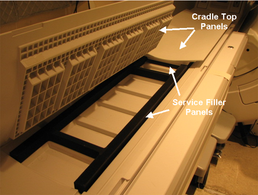
-
(For flat table) Place the TLT phantom and sphere
on the flat table. Position the phantom in the center of the cradle
and center it on the PA coil. To achieve the best test measurement,
the phantom must be located in the center (long direction) of the
cradle.Note:
The MR table in the figure is a flat (GEM) table.
(For curved table) Place the TLT phantom directly on the cradle.
Figure 2. TLT Phantom and Sphere on Flat Table 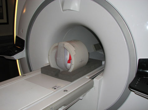
- Start the B0 Drift tool:
- (For non-proprietary service tools) From the Common Service Desktop, select Calibration > B0 Drift Calibration. Select Click here to start this tool.
The B0 Drift window appears.
Figure 3. B0 Drift Window with X, Y, and Z Axes Highlighted Non-Proprietary 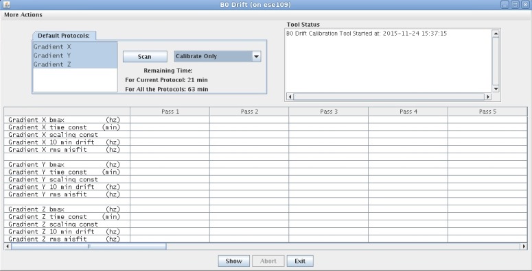
- When B0 drift calibration completes, a screen displays the data
for each axis.
Figure 4. Data from B0 Calibration 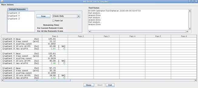
Finalization
Remove service equipment, phantom, and head coils.
(For curved table) Remove service filler panels from each cradle top panel.