
- Discovery MR750w and SIGNA™ Architect T 3.0T System Service Methods
- 5690002-2EN Revision 4
- 00000018WIA3000CE20GYZ
- id_131065283.0
- Aug 29, 2019 1:48:47 AM
Body coil isolation
Prerequisites
| Required persons | Preliminary requirements | Procedure | Finalization |
|---|---|---|---|
| 1 | 0 minutes | 30 minutes | 0 minutes |
| Item | Quantity | Effectivity | Part number | Manufacturer |
|---|---|---|---|---|
| Non Magnetic Tool including Allen Wrench to adjust body coil RL position | 1 | - | - | - |
| Step Gauge (Placed at front mounting bracket) | 1 | - |
5397937 | - |
| ||||
| Condition | Reference | Effectivity |
|---|---|---|
| LOTO FOR XRFD Amp and PEN Cabinet is applied | - | - |
| Split Bridge and Front / Rear End Bell are removed. | - | - |
Body coil RL alignment
Procedure
- Find Step Gauge which is placed at front mounting bracket and
remove it.
Figure 1. Step Gauge Location 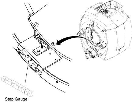
- Note: Body Coil shape may not be perfect circle and it might be slightly ellipse. So, there are two specs for RL alignment and AP alignment.At front end, check the gaps between Body Coil and Inner Gradient Coil at 2 horizontal measurement locations (90deg/3 o’clock and 270deg/9 o’clock) using Step Gauge. Slide the Step Gauge between the hard body coil outside diameter and the hard gradient coil inside diameter until it will not slide any further. The value on the last step to slide between the body coil and the gradient coil indicates the gap. The step gauge is marked in ‘mm’.
Spec: Differential of Gap (90deg/3 o’clock) and (270deg/9 o’clock) ≤ 0.5mm (Identical or no more than 1 Adjacent Step).
Options of 1 Adjacent Step: a) 9 & 9.5; b) 9.5 & 10; c) 10 & 10.5; d) 10.5 & 11, e) 11 & 11.5
Figure 2. Step Gauge 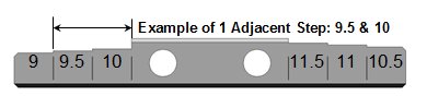
Table 5. Gap option matrix If gap at 90deg/3 o’clock = Then gap at 270deg/9 o’clock must = 9 9 or 9.5 9.5 9 or 9.5 or 10 10 9.5 or 10 or 10.5 10.5 10 or 10.5 or 11 11 10.5 or 11 or 11.5 11.5 11 or 11.5 Figure 3. GAP check 1 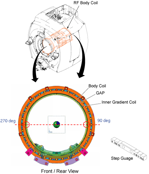
- If the gaps does not satisfy the specification in step 2, adjust
RL position using RF Body Coil support to meet the specification of
step 2.
Figure 4. Adjustment of RF body coil support (RL position) 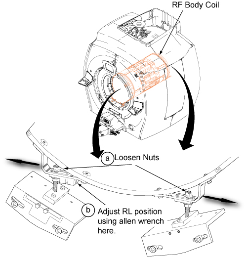
Body coil AP alignment
Procedure
- At front end, check the gaps between Body Coil and Inner Gradient
Coil at 3 vertical measurement locations (0 deg/12 o’clock,
120 deg/4 o’clock, and 240 deg/8 o’clock) using Step Gauge. Spec:
- Differential of Gap (0deg), Gap (120 deg), and Gap (240 deg) ≤ 0.5mm (Identical or no more than 1 Adjacent Step).
Options of 1 Adjacent Step: a) 9 & 9.5; b) 9.5 & 10; c) 10 & 10.5; d) 10.5 & 11, e) 11 & 11.5
- Also ensure Gap (0deg/12 o’clock) ≤ Gap (120 deg/4 o’clock) and Gap (0deg) ≤ Gap (240 deg/8 o’clock)
Figure 5. Step Gauge Table 6. Gap Option Matrix If gap at 0 deg/12 o’clock = Then gap at 120 deg/4 o’clock must = Then gap at 240deg/8 o’clock must = 9 9 or 9.5 9 or 9.5 9.5 9.5 or 10 9.5 or 10 10 10 or 10.5 10 or 10.5 10.5 10.5 or 11 10.5 or 11 11 11 or 11.5 11 or 11.5 11.5 11.5 11.5 Figure 6. GAP check 2 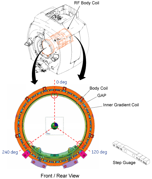
- Differential of Gap (0deg), Gap (120 deg), and Gap (240 deg) ≤ 0.5mm (Identical or no more than 1 Adjacent Step).
- If the gaps does not satisfy the specification in step 1, adjust
AP position using RF Body Coil support to meet the specification of
step 1.
Figure 7. Adjustment of RF body coil support (AP position) 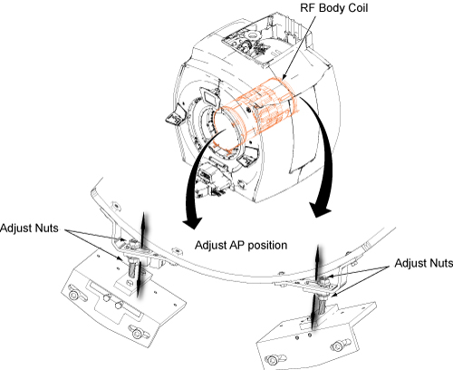
Final check
Procedure
- 1. After re-tightening any loosened nuts, check RL position and AP position of Front End and Rear End again per Body coil RL alignment and Body coil AP alignment and adjust the position if necessary until the specifications are satisfied.
- Restore Step Gauge at front mounting bracket.
- If you are doing RF Coil Replacement Procedure, return to the original procedure. Changing RF coil isolation/alignment will affect coil tuning
Finalization
Finalization
No finalization steps.