
- Discovery MR750w and SIGNA™ Architect T 3.0T System Service Methods
- 5690002-2EN Revision 4
- 00000018WIA3091CE20GYZ
- id_131065293.2
- Feb 4, 2021 7:52:09 PM
Body coil tuning (network analyzer kit 5336593-2)
Prerequisites
| Required persons | Preliminary requirements | Procedure | Finalization |
|---|---|---|---|
| 1 | - | - | - |
| Item | Quantity | Effectivity | Part number | Manufacturer |
|---|---|---|---|---|
| Network Analyzer Service Tool Kit | 1 | - | 5336593 (5336593-2, 5336593-3 or 5336593-4) | - |
| Body Loader with Sphere Phantom | 1 | - | 2371511 | - |
| ||||
| Condition | Reference | Effectivity |
|---|---|---|
|
Body Coil Isolation is done. | - | - |
|
System must be in scanning condition | - | - |
About this task
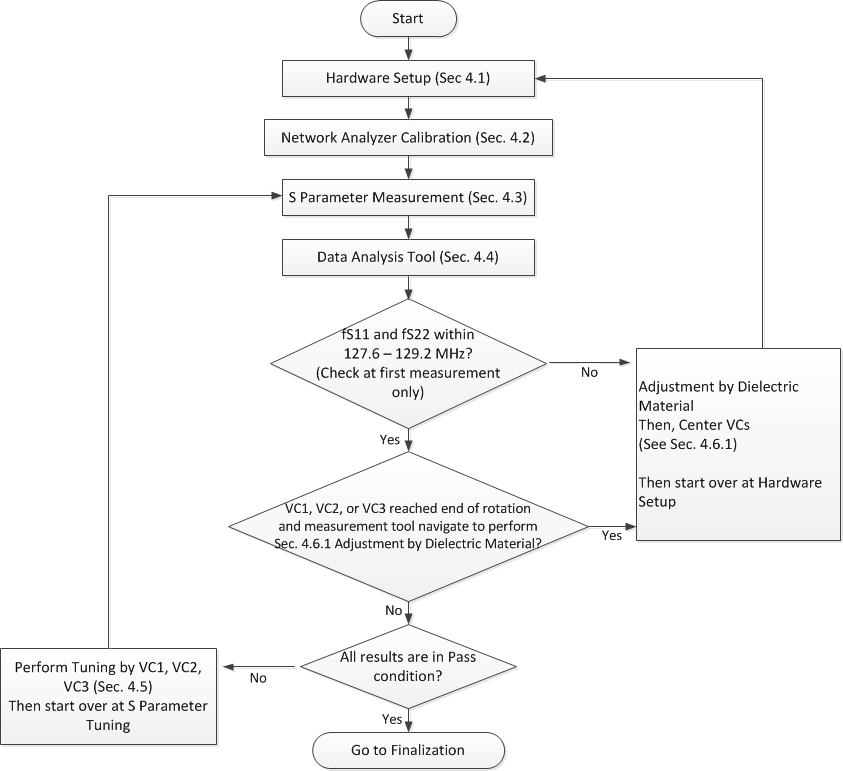
Hardware setup
Procedure
- Do the following sub-steps to set up any body coil scan on scan window to set up driver module body BIAS mode.
- On the Exciter/Ref Clock module located in the Pen cabinet, set the RF ENB switch to DOWN (Disable).
Figure 2. Exciter/Ref clock module 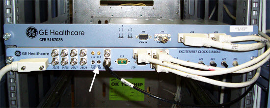
- On the Exciter/Ref Clock module located in the Pen cabinet, set the RF ENB switch to DOWN (Disable).
- Remove the bridge cover, right center cover, and right rear cover.
Figure 3. Remove covers 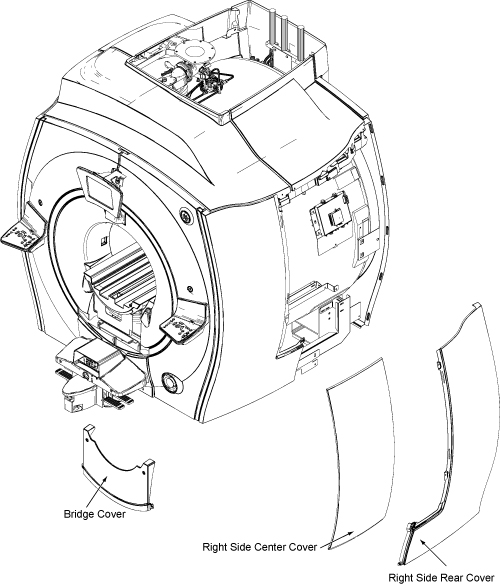
- Place the body loader with phantom on the bridge, and push it to the magnet center so that it is centered right-to-left on the bridge. The front edge of the body loader is 835 mm (33 inches) away from the front edge of the bridge.
Figure 4. Body loader setup 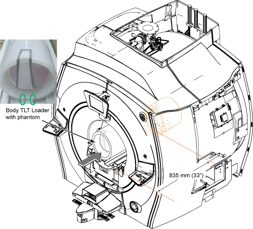
Calibration of network analyzer
Procedure
Connect bias T at port 1 and port 2. Do not connect the bias cable at this time.CAUTION 
Figure 5. Bias T Installation 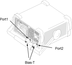
- Note:Power ON the network analyzer.
It is recommended that you connect a mouse to one of the USB ports on the network analyzer.
If you do not use a mouse, use the hard keys. For example, select [Menu] hard key and then use arrow (<, >) hard keys to navigate and highlight, and [ENTER] hard key to select from menu.
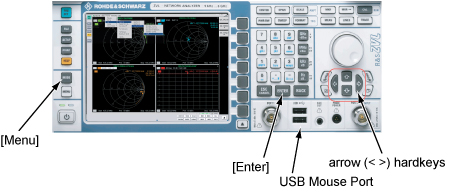
Figure 6. Power ON 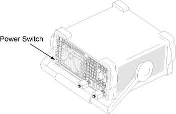
- From the Nwa-Setup menu, select External Tools > Calibration.lnk.
Figure 7. Nwa-Setup menu 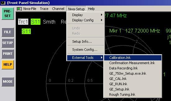
- Connect N(m) to N(m) coaxial cable to bias T of port 1.
Figure 8. Cable connection 1 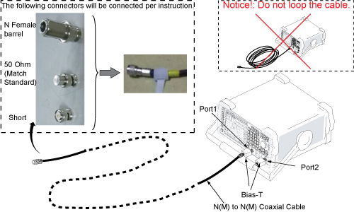
Do not touch cable ends. Minimize human interaction during network analyzer calibration, because this can change the impedance of the calibration setup.
Do not cross the cables. Route the cables so they are parallel and separated from each other as much as possible.
Note: It is recommended that the 50 ohm load (Match Standard) be measured with a DVM to confirm that it is operational. - When the following message is displayed, connect female barrel and “BNC female to N male” to the end port 1 cable and press Enter (or click OK). Do not make any changes until prompted.
Figure 9. Connect OPEN message 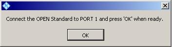
It takes about 15 seconds for the next message to display.
- When the following message is displayed, connect short to “BNC female to N male” and press Enter (or click OK).
Figure 10. Connect SHORT Message 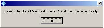
- When the following message is displayed, remove short. Connect 50 ohm load and press Enter (or click OK).
Figure 11. Connect MATCH Message (50 Ohm Load) 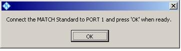
- Connect port 1 and port 2 cables through female barrel.
Figure 12. Cable connection 2 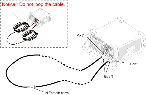
- When the following message is displayed, press Enter (or click OK).
Figure 13. Connect THROUGH message 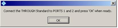
Calibration is complete.
The buttons at the right side of the screen are displayed after calibration is completed.
Figure 14. Buttons at screen right 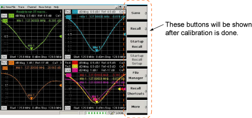
Connect the cables to the network analyzer as shown below.Warning 
Figure 15. Hardware setup 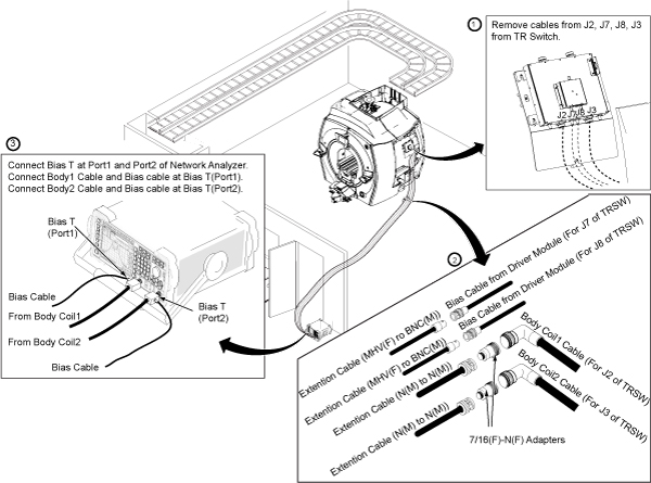
S-Parameter measurement
Operation check
Procedure
- From the Nwa-Setup menu, select External Tools > Rough Tuning.lnk.
Figure 16. Rough tuning selection 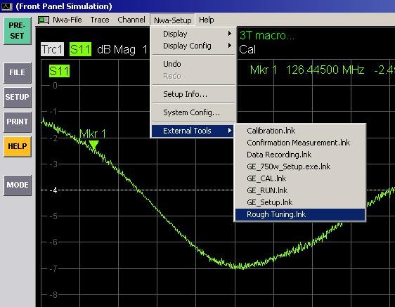
- Check that plots are shown as follows. If not, check the bias cables.
Figure 17. Rough tuning plots 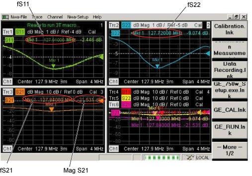
Confirmation measurement
Procedure
- From the Nwa-Setup menu, select External Tools > Confirmation Measurement.lnk.
It takes about 30 seconds for the Measurement Results screen to display.
Figure 18. Measurement results 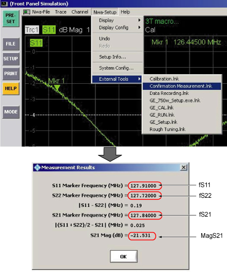
Data analysis
Procedure
Tuning
About this task
Procedure
- From Nwa-Setup menu, select External Tools > Rough Tuning.lnk.
Figure 19. Rough tuning - Read fS11, fS22, or fS21/MagS21 values.
Figure 20. Rough tuning plots To show a single waveform window in a display, double-click on the desired window to expand it. To return to the four-window display, double-click again on the window.
- Turn VC1, VC2, or VC3 using stick to tune fS11, fS22, or fS21, respectively, so that fS11, fS22, fS21 are as close as the target frequency in the Data Analysis Tool.
1 clockwise turn of VC1 => -10 kHz to -20 kHz of fS11, 1 clockwise turn of VC2 => -10 kHz to -20 kHz of fS22
1 clockwise turn of VC3 => +15 kHz to +40 kHz of fS21. fS11 and fS22 are slightly decreased by tuning VC3 clockwise. Reconfirm fS11 and fS22 values after VC3 adjustment.
Figure 21. Tuning 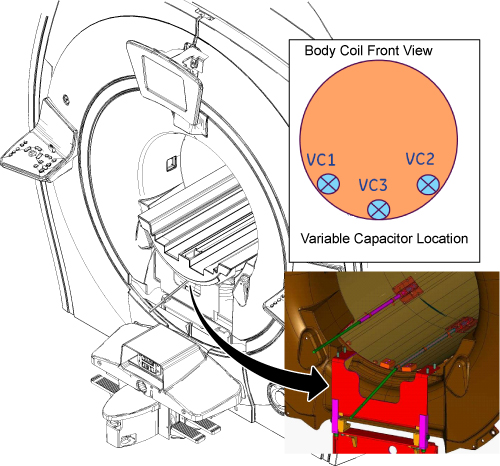
Further adjustment
Adjustment by dielectric material
About this task
- fS11, fS22, or fS21 < 127.6 MHz at the first measurement of S-Parameter measurement.
- fS11, fS22, or fS21 > 128.2 MHz at the first measurement of S-Parameter measurement.
- VC1, VC2, or VC3 reached the end of rotation and the Data Analysis Tool indicates you should perform adjustment by dielectric material.
Procedure
- Change dielectric material according to the site conditions.
- fS11 or fS22 > 128.2 MHz: Increase dielectric material by one step.
-
VC reached end of rotation and fS11 or fS22 >128.05 MHz, or fS21 > (fS11 + fS22)/2 + 0.05 MHz: Increase dielectric material by one step.
Figure 22. Increase dielectric material by one step 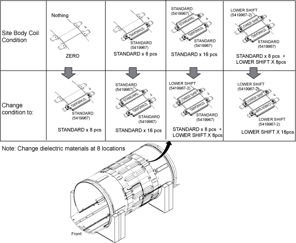
- fS11 or fS22 < 127.6 MHz: Decrease dielectric material by one step.
- VC reached the end of rotation and fS11 or fS22 < 127.75 MHz, or fS21 < (fS11 + fS22)/2 – 0.05 MHz: Decrease dielectric material by one step.
Figure 23. Decrease dielectric material by one step 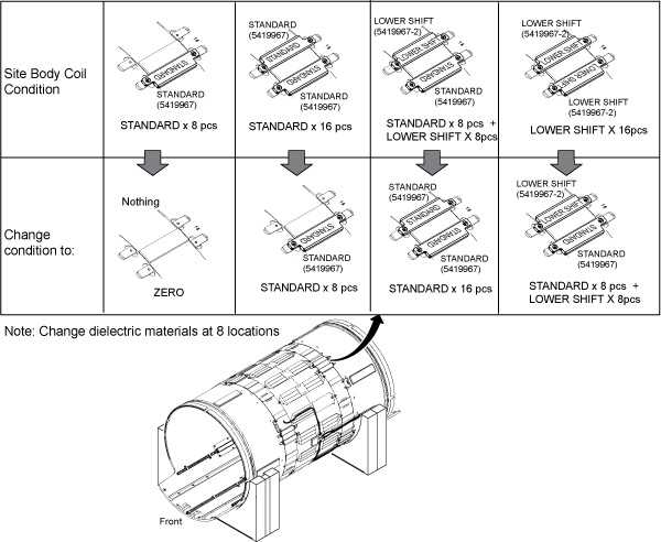
If 16 lower shift pieces are attached on body coil, no additional material is needed for replacement.
The body coil FRU includes dielectric materials for adjustment. There is no need to order the dielectric material FRU kit. If dielectric material is required after XRMw replacement, order the dielectric material FRU kit (5423650).
When replacing dielectric material to “Standard x 8 pieces” or “Standard x 8 pieces + Lower Shift x 8 pieces”, the order is important. Follow the illustration below.
Figure 24. Dielectric Material Order 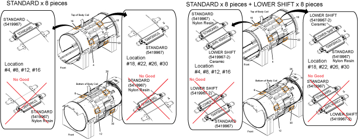
- Inspect airflow gaskets (5404530 and 5404530-2). Gaskets should be bonded along entire length.
Figure 25. Air flow gasket 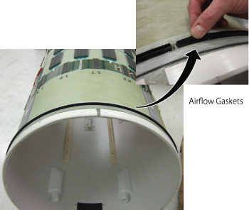
Adjustment of MagS21
Procedure
- If MagS21 fails but other values are within specification, perform Body Coil Isolation.
- If MagS21 fails after body coil isolation and body coil tuning, replace the body coil.
Finalization
Procedure
- Select End Exam from the scan window menu (End/End Exam).
- Restore the cables, phantom, and enclosure.
- Run TR Dynamic Disable Calibration.
- Run System gain calibration.
- Run DD Quadrature Calibration .
- Run Echo Planar Test (EPT).
- Do a quick head and body scan to ensure the system is functioning properly.