
- Discovery MR750w and SIGNA™ Architect T 3.0T System Service Methods
- 5690002-2EN Revision 4
- 00000018WIA308EBE20GYZ
- id_131065003.2
- Dec 9, 2019 1:21:08 PM
MR 750 Body Coil Centering
Prerequisites
| Required persons | Preliminary requirements | Procedure | Finalization |
|---|---|---|---|
| 2 | Not Applicable | 8 hours each (only if coil alignment is necessary), 3 hours (if no coil alignment is necessary) minutes | Not Applicable |
| Item | Quantity | Effectivity | Part number | Manufacturer |
|---|---|---|---|---|
| Non-Magnetic Level — Non-Magnetic, approximately 90cm (3 ft) in length. | 1 | - | - | - |
| Non-Magnetic Level — Small non-magnetic level, approximately 7.5cm (3 inches) in length. | 1 | - | - | - |
| 3T Uniformity Phantom Kit | 1 | - |
5315746 — Order through your normal pooled tool ordering process. | - |
| Network Analyzer Service Tool | 1 | - |
5336593-2, or 5336593-3 — Order through your normal pooled tool ordering process. | - |
| Bridge Height Gauge | 1 | - |
5346292 — Part was shipped with the system. Also available as a FRU. | - |
| Gap Tool, End bell to Body Coil | 1 | - |
5391159 — Part available as FRU | - |
| Arc Detection Kit | 1 | - |
5401455-2 — Order through your normal pooled tool ordering process. ONLY if Body Coil Tuning is needed. | - |
| Field RF Coil Tuning Kit | 1 | - |
5311727 — Order through your normal pooled tool ordering process. ONLY if Body Coil Tuning is needed. | - |
| Software, RF Tuning Kit | 1 | - |
5352480 or 5535261 — Provided as part of Body Coil Tuning and Arc Detection Stress Test class. | - |
| Item | Quantity | Effectivity | Part number | Manufacturer |
|---|---|---|---|---|
| Tie wraps — Used to secure the elliptical drive cabling. | 1 | - | - | - |
| Item | Quantity | Effectivity | Part number | Manufacturer |
|---|---|---|---|---|
| Body Coil Centering Hardware | 1 | - |
5506884 — Part available as FRU | - |
| Condition | Reference | Effectivity |
|---|---|---|
|
System must be within specification prior to performing this procedure. Both SPT Body and EPI White Pixel Test must have a PASS result. | - | - |
About this task
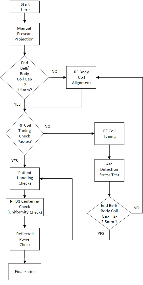
This document addresses customer complaints related to shading in breast and pelvic imaging on MR750 systems only. It has been shown that the main source of shading in 3T systems is dielectric effect, which distorts the B1 homogeneity.
-
Performance Baseline
-
Manual Prescan Projection
-
End bell/Body coil gap check
-
RF Tuning check
-
Coil Alignment (if needed), RF coil tuning (if needed), arc detection stress test (if needed)
-
Patient Handling checks
-
RF B1 centering check (uniformity and power check)
-
Finalization
Body Coil Tuning requires additional training.
The RF Coil Tuning and Arc Detection Stress Test sections of this procedure can only be performed by trained personnel, who have successfully completed GE Healthcare’s training class for Body Coil tuning and Stress Test (GEHC-TECH-AMSC-MR5037).
This procedure applies ONLY to MR750 magnets operating in normal (forward) ramped polarity.
Manual Prescan Projection
Procedure
- Place the Elliptical Phantom (2) and phantom holder (1) at the center (S/I) of the cradle. Set the angle of the phantom to 0 degrees. Landmark on the center of the phantom. Press the LANDMARK button at the keypad on the front of the magnet enclosure, then press ADV TO SCAN button.
Figure 2. Elliptical Phantom Positioning 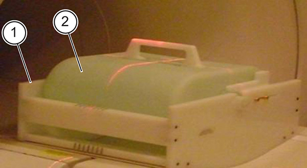
ITEM DESCRIPTION 1 Phantom holder 2 Elliptical phantom - When the single scan completes, two pop-ups appear. One is titled “Profile of ePhantom”; the other is titled “Uniformity Plot of ePhantom.”
Figure 3. Profile of ePhantom 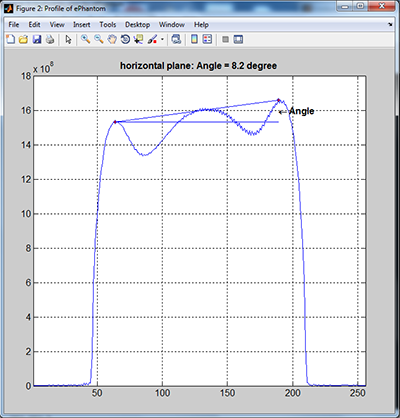
Figure 4. Uniformity Plot of ePhantom 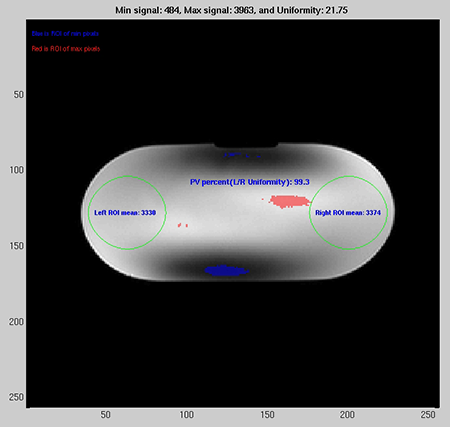
End Bell/Body Coil Gap Check
Procedure
- Check the gap between the rear end bell and the RF body coil using the gap tool. Check the gap at several locations across the circumference to ensure it is uniform all around. The gap should be between 2 – 2.5 mm (ideal gap is 2 mm).
Figure 5. Gap Check Using Gap Tool 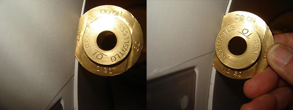
Figure 6. Example of Proper Gap Between Front/Rear End bells and RF Body Coil 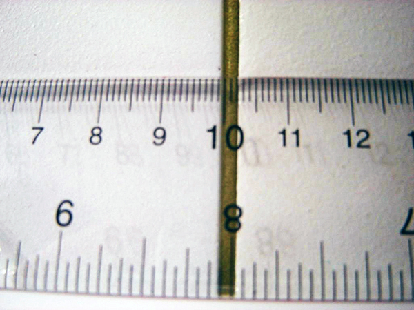
Figure 7. Examples of Improper Gap Between Front/Rear End bells and RF Body Coil 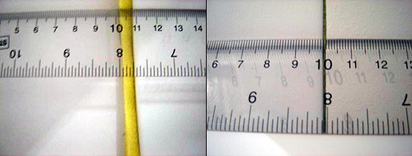
RF Coil Tuning Check
Procedure
- Note:Refer to the Field Service RF Tuning Instructions by downloading ltest from the online documentation library for the steps necessary to take and analyze frequency measurements.
This procedure should only be performed by trained personnel, who have successfully completed GE Healthcare's training class for the Body Coil Stress Test.
- If the tuning check passes, proceed to Patient Handling Checks. If the tuning check fails, proceed to RF Coil Tuning.
Patient Handling Checks
Procedure
- Check the bridge height at the front and rear of the magnet using the bridge height gauge that was originally shipped with the dock assembly. This measurement should be taken from the bottom surface of the belt groove in the center of the bridge. The bridge height specification range is 502 – 505 mm (although a bridge height of 505 mm is preferred).
Figure 8. Bridge Height Check 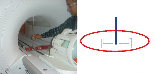
-
If the bridge height is not within specification, adjust the M10 nylon nuts at the bottom of the bridge support upper bracket to raise and lower the bridge to attain the 502 – 505 mm specification (a height of 505 mm is preferred). The rear pedestal feet can also be adjusted to attain the bridge height specification of 502 – 505 mm (a height of 505 mm is preferred).
-
At bridge height of 502-505 mm check to make sure that the bottom of the bridge is not in contact with any RF coil component (like the bulkhead).
-
The bridge height gauge is also available as a FRU in case you’re unable to locate the original one shipped with the dock assembly.
-
- Check the bridge alignment in the z-direction (in/out of the bore) and ensure it is flush with the end bells +/-3 mm. Adjustments can made at the L-brackets.
Figure 9. Bridge Alignment in the z-direction 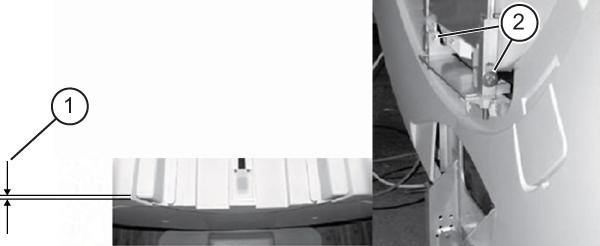
ITEM DESCRIPTION 1 +/- 3mm 2 L-brackets
RF Coil B1 Centering Check (Uniformity and Power Check)
Procedure
- Note:Landmark on the center of the phantom. Press LANDMARK at the keypad on the front of the magnet enclosure, then press ADV TO SCAN.
Allow the phantom solution to settle for 5 minutes prior to scanning. This will prevent flow-related artifacts, which may affect the test results.
Figure 10. Elliptical Phantom Positioning - In a command window type the following: cd /usr/g/service/mclass/uniformity touch .uniformity_enable run_uniformity_tool.
The Uniformity Tool GUI pops up.
Note:The scan status and result are displayed on Uniformity Tool GUI Status dialog box. All buttons are inhibited during scan. Only Abort Scan button is available during scan. All buttons are available when scan is idle. Abort Scan button is inhibited when scan is idle. Do not re-lANDMARK between scans.
Figure 11. Uniformity GUI and Status 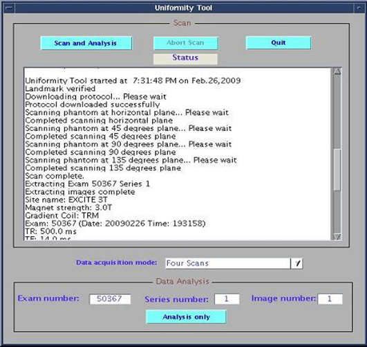
- Choose Yes when asked if user has landmarked.
Figure 12. Landmark Message 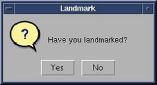
- Select Continue when asked to position the phantom at horizontal position.
Figure 13. Horizontal Position 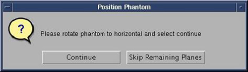
- When asked to position the phantom, rotate phantom to 45-degree plane and choose Continue.
Figure 14. 45 Degree Position 
- When asked to position the phantom, rotate phantom to 90-degree plane and choose Continue.
Figure 15. 90 Degree Position 
- When asked to position the phantom, rotate phantom to 135-degree plane and choose Continue .
Figure 16. 135 Degree Position 
- During the scan, record the RF amplifier Peak Forward Power value in the table below. Scanner should stop after scanning 135-degree position and automatically process results.Note:
Use the printPower function to read the Peak Forward Power in each orientation: open a C-shell, type mgd_term to bring up the SCP window, type printPower and record the Body Peak value listed in the window in the table below.
Figure 17. Result Plot 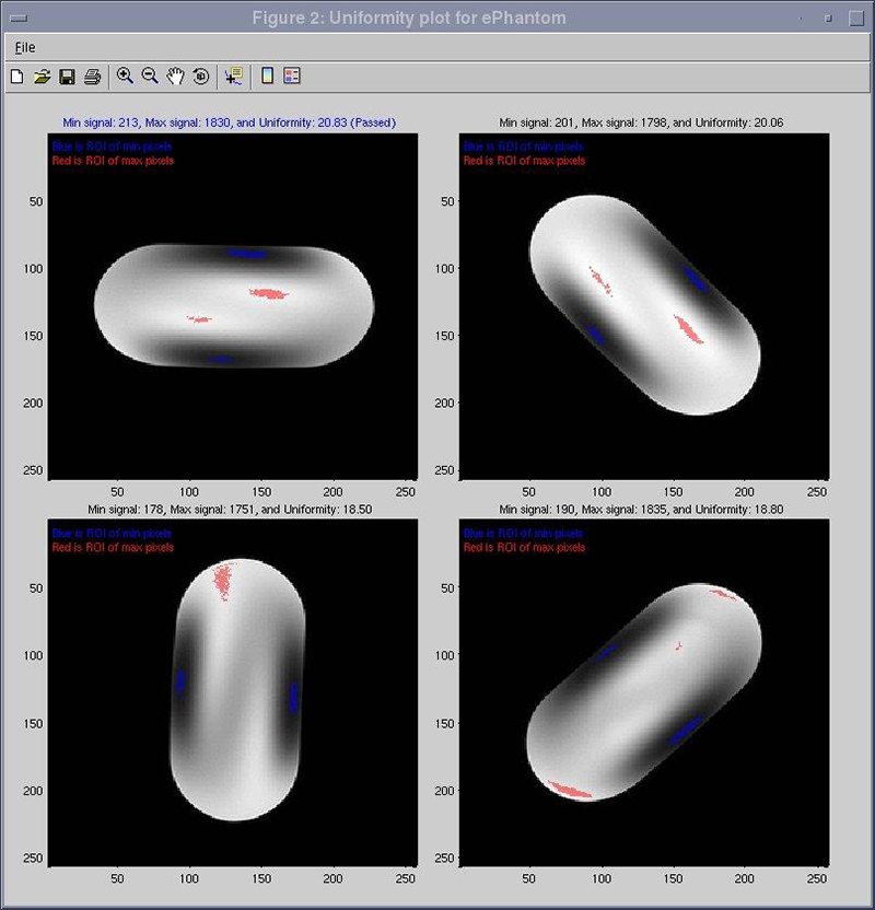
RF Body Coil Alignment
Procedure
- Perform RF Body Coil Alignment - Centering Pads.Note:Older style body coils might have a one-piece strip that was used for centering. This strip must be removed and the new feet that are provided in the FRU kit will be utilized. If the strip is not present and feet are used, follow the instructions in RF Body Coil Alignment - Centering Pads but do not proceed to Finalization. When complete, proceed to RF Coil Tuning Check RF Coil Tuning Check.
Figure 18. Old Style Shims 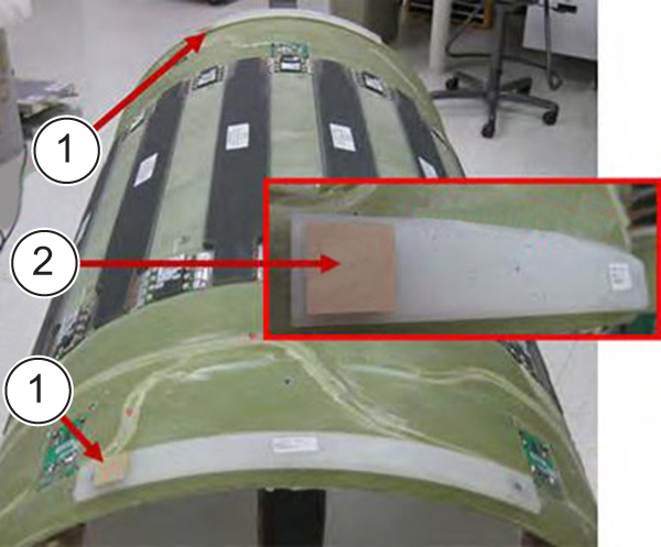
ITEM DESCRIPTION 1 Coil shim placement 2 Close-up view Remove any shim and centering spacer adhesive before installing feet.Figure 19. Shim Feet Preparation 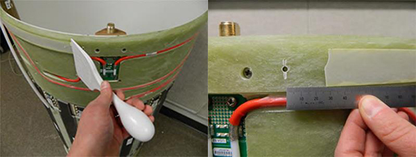
Figure 20. Installed Shim Feet 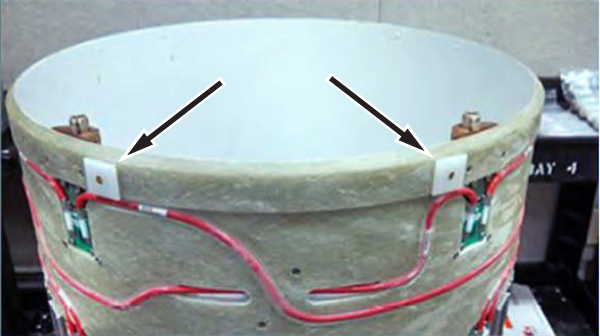
RF Coil Tuning
About this task
RF Coil Tuning procedure:
-
This procedure should only be performed by trained personnel, who have successfully completed GE Healthcare's training class for the Body Coil Stress Test.
-
Please refer to the Field Service RF Tuning Instructions for the steps necessary to tune the RF Body Coil. Once the RF Coil Tuning is complete, proceed to Arc Detection Stress Test (Arc Detection Stress Test).
Arc Detection Stress Test
About this task
Arc Detection Stress Test procedure:
-
This procedure should only be performed by trained personnel, who have successfully completed GE Healthcare's training class for the Body Coil Stress Test.
-
Please refer to latest Service Methods for the 3.0T Arc Detection Test With Body Coil Stress procedure.
-
After the Arc Detection Stress Test is completed, re-check the gap between the endbells and RF Body Coil. Re-install the front and rear endbells. If you cannot achieve the gap spec of 2 – 2.5 mm, see RF Body Coil Alignment. If the gap is acceptable, proceed to Patient Handling Checks.
Reflected Power Check
Procedure
- From the C-Shell, view the first upmdata file, by typing: view upmdata_upm1.txt then hit Enter.
The first upmdata file will be displayed. Scroll down towards the end of the file until you find the Body Channel section.
Figure 21. UPM Data File 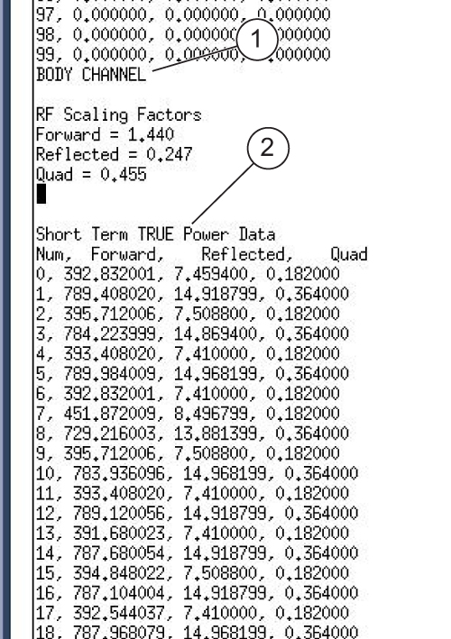
ITEM DESCRIPTION 1 Body Channel section 2 Data
Uniformity Measurements
About this task
Repeat the Baseline Uniformity Measurements for only the Elliptical Phantom Position of 0 degrees following the steps in Uniformity Test and record the data in the Final Phantom Scan Data Table.
| Elliptical phantom position | Exam/Series/Image | TG | Power | Uniformity | Uniformity Spec | |||
| Min | Max | U | Target | Absolute min | ||||
| 0 |
U > 30
If elliptical hardware is installed. | |||||||
| 0 |
U > 15
If elliptical hardware is not installed. | |||||||