
- 00000018WIA302AB030GYZ
- id_123738661.12
- Dec 2, 2019 3:46:57 PM
HP Z420 Lower Level FRU Replacement
Prerequisites
| Required persons | Preliminary requirements | Procedure | Finalization |
|---|---|---|---|
| 1 | - | As required | 30 minutes |
| Item | Quantity | Effectivity | Part number | Manufacturer |
|---|---|---|---|---|
| Standard FE Toolkit | 1 | - | - | - |
| 4 mm Hex Key Wrench | 1 | - | - | - |
| ESD Mat and Wrist Strap | 1 | - | - | - |
| Item | Quantity | Effectivity | Part number | Manufacturer |
|---|---|---|---|---|
| Hard drive | 3 | hard drive replacement |
See FRU manual. | - |
| DVD drive | 1 | DVD drive replacement |
See FRU manual. | - |
| Battery, Type 2032 Coin, 3 V, Lithium | 1 | battery replacement |
See FRU manual. | - |
| Condition | Reference | Effectivity |
|---|---|---|
|
Access to both the front and rear of the operator console is required. Move the console away from walls and remove obstacles in room. | - | - |
About this task
Overview
This procedure describes the steps to replace lower level FRUs in the HP Z420 host PC, including:
-
DVD drive
-
Hard drive
-
CMOS battery
Workstation Service Preparation
Procedure
Remove the host computer from the GOC.CAUTION Figure 1. Removing Computer from Brackets 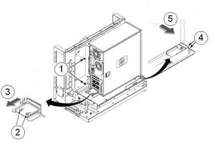
Item Description 1 Remove the two screws securing the back bracket to the GOC. 2 Loosen the two screws on the back slide plate. 3 Slide the plate backward. 4 Loosen the two screws on the side slide plate. 5 Slide the plate in the direction of the arrow. Notice 
Remove the two screws that secure the left side panel to the rear of the PC.Notice
DVD Drive Replacement
Procedure
- Remove the front panel on the computer by gently unsnapping
the plastic locks located on the left side and pulling on the left
side of the cover.
- Pull the cover out just far enough to disengage the locks. If you pull them out too far, you can damage the locks on the right side of the cover.
- Push the cover slightly to the right as you pull out on the cover.
- Set the front cover aside in a safe location.
Figure 2. Remove Front Panel 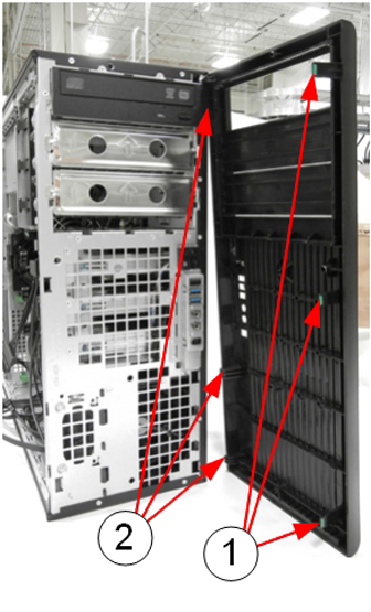
Item Description 1 Release plastic locks 2 Plastic hinges (breakable) - Locate and unplug the power/data cable harness (D4) on the back
of the DVD drive.
Figure 3. Power/Data Cable Harness (D4) on Rear of DVD Drive 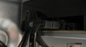
- Pull out the plastic lock located on the left side of the PC
and carefully slide out the DVD drive.
Figure 4. Remove DVD Drive 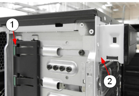
Item Description 1 Plastic lock 2 DVD drive being removed
Hard Drive Replacement
About this task
The HP Z420 has three hard drives.
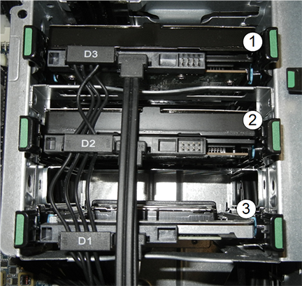
| Item | Description |
| 1 | Top slot, power connection D3 |
| 2 | Middle slot, power connection D2 |
| 3 | Bottom slot, power connection D1 |
Procedure
Remove the drive from the carrier by twisting the carrier slightly to disengage the 4 pins holding the hard drive into the carrier.CAUTION Figure 6. Hard Drive and Carrier 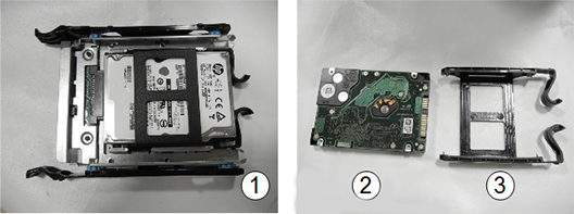
Item Description 1 Hard drive in slot carrier 2 Hard drive 3 Carrier
CMOS Battery Replacement
Procedure
- Press on the green tabs of the card in slot 4 and remove the
card.
Figure 7. Slot 4 Card Removal 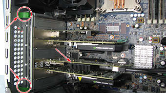
- Locate the CMOS battery on the HP computer system board.
Figure 8. CMOS Battery Location 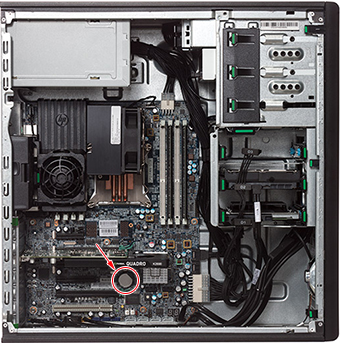
- Remove the old CMOS battery. Release the CMOS battery from its
holder by pulling back on the spring clip. Do NOT put pressure on
the holder.Note:
Two small screwdrivers may be needed – one to push the battery out of the grip, the other to lift the battery up.
Figure 9. CMOS Battery Removal 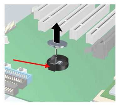
Reinstalling Host Computer in GOC
Procedure
Powering on Operator Console
Procedure
- Remove LOTO.
- Power ON the GOC at the rear of the GOC and then power up the host PC.
-
IF THE CMOS BATTERY WAS REPLACED, press F10 as soon as the hp invent screen
appears. Setup displays at the lower right of
the screen. Perform the following steps: