
- 00000018WIA30AED030GYZ
- id_123749251.1
- Jul 5, 2019 10:03:32 PM
GOC Audio Assembly Replacement - New GOC
Prerequisites
| Required persons | Preliminary requirements | Procedure | Finalization |
|---|---|---|---|
| 1 | Not Applicable | 15 minutes | 30 minutes |
| Item | Quantity | Effectivity | Part number | Manufacturer |
|---|---|---|---|---|
| Phillips Screwdriver | 1 | - | - | - |
| Item | Quantity | Effectivity | Part number | Manufacturer |
|---|---|---|---|---|
| GOC Audio Box | 1 | - |
2395043 or 2395043-2 | - |
| ||||
| Condition | Reference | Effectivity |
|---|---|---|
|
The host computer and the GOC audio assembly must be powered off. | - | - |
Procedure
- Note:Remove the two screws that secure the right side panel, and lift the panel off to expose the GOC audio assembly (GOCAA).
The PDU must be powered down completely to prevent damage to system electronics.
Figure 1. Exposing GOC Audio Assembly 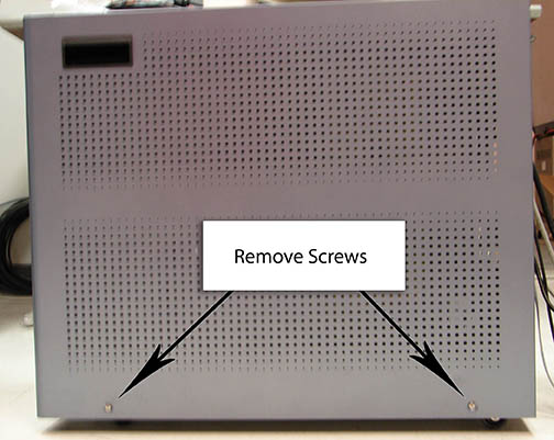 Note:
Note:Take care not to strain the short grounding lead that runs between the panel and the main chassis.
Figure 2. Ground Lead 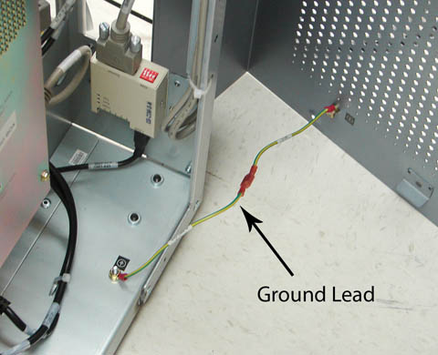
- Disconnect the power cord from the GOCAA.
Figure 3. Disconnecting Power Cord and Cables 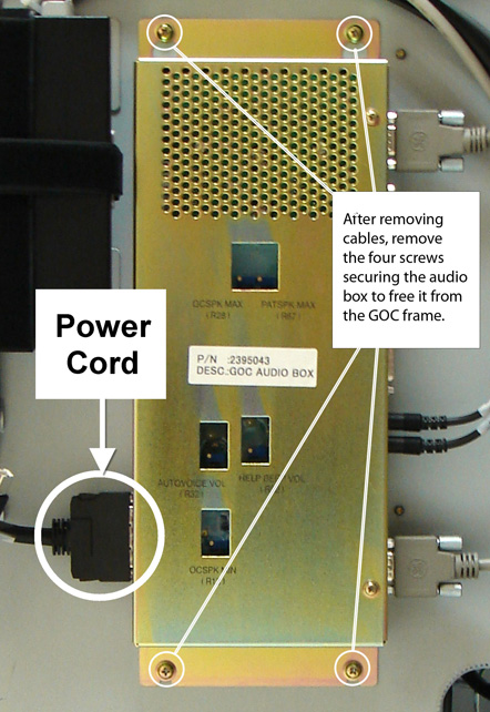
Finalization
- Remove LOTO from the PGR/PDU and apply power to the PDU. See the MR Service Safety Manual, PN 5452735.
- Perform Intercom Adjustment for the newly installed GOC audio box.
- Reboot the host computer.
- Perform a scan.