
- 00000018WIA3055E030GYZ
- id_123736111.9
- Jul 5, 2019 6:08:29 PM
HP Z400 Lower Level FRU Replacement
Prerequisites
| Required persons | Preliminary requirements | Procedure | Finalization |
|---|---|---|---|
| 1 | - | As required | 30 minutes |
| Item | Quantity | Effectivity | Part number | Manufacturer |
|---|---|---|---|---|
| Standard FE Toolkit | 1 | - | - | - |
| ESD Mat and Wrist Strap | 1 | - | - | - |
| Maintenance label | 1 | - | - | - |
| Item | Quantity | Effectivity | Part number | Manufacturer |
|---|---|---|---|---|
| Battery, Type 2032 Coin, 3 V, Lithium | 1 | Battery replacement |
See FRU manual. | - |
| Graphics Card | 1 | Graphics Card replacement |
See FRU manual. | - |
| Memory Module | 1 | Memory Module replacement |
See FRU manual. | - |
| DVD drive | 1 | DVD drive replacement |
See FRU manual | - |
| Hard disk drive | 1 | hard disk drive replacement |
See FRU manual | - |
About this task
Overview
This procedure describes the steps to replace lower level FRUs in the HP Z400 host PC.
Workstation Service Preparation
Procedure
- Remove the two screws on the left side panel of the GOC.
Figure 1. Screws on Left Side Panel 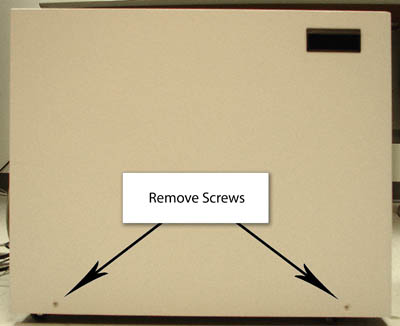
- Disconnect the short ground lead that connects the side panel
to the GOC main chassis at the center of the lead.
Figure 2. Ground Lead 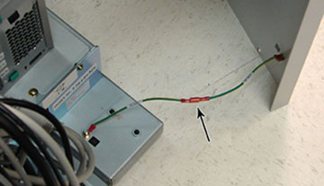
Remove all the cables connected to the computer, ensure they are properly labeled, and note their locations for reattachment.CAUTION Figure 3. HP Z400 Cable Configuration 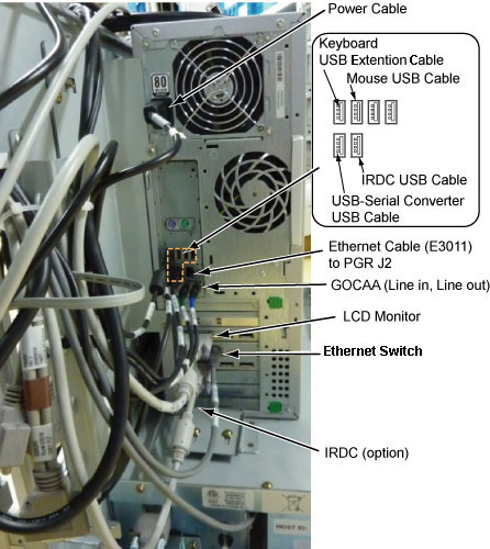
- Loosen the strap and remove the hook.
Figure 4. Removing Strap 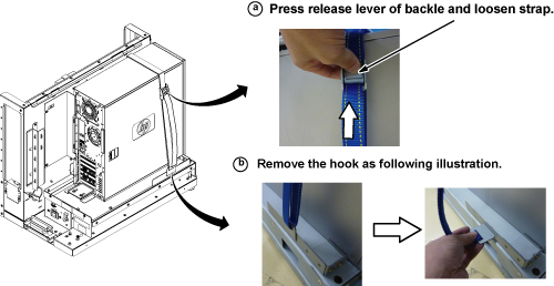
- Remove the Z400 computer as follows:
- Loosen the two screws on the side slide plate, and slide the
plate in the direction of the arrow.
Figure 5. Removing HP Z400 Computer 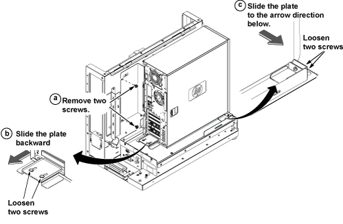
- Loosen the two screws on the side slide plate, and slide the
plate in the direction of the arrow.
Notice 
Remove the two screws that secure the left side panel to the rear of the PC.Notice Figure 6. Screws on PC 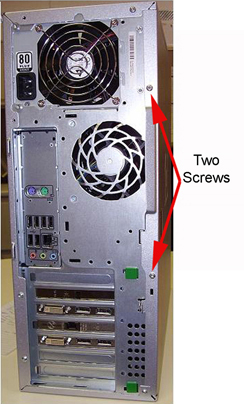
- Remove the left side panel of the PC by pulling the latch out,
and sliding the cover back. Set the cover aside in a safe location.
Figure 7. Latch on Side Panel 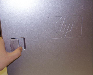
Replacing CMOS Battery
Procedure
- Locate the CMOS battery on the HP computer system board.
Figure 8. CMOS Battery Location 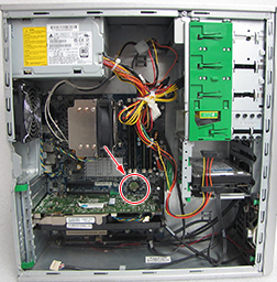
- Remove the old CMOS battery. Release the CMOS battery from its
holder by pulling back on the spring clip.
Figure 9. CMOS Battery Removal 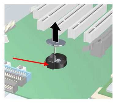
Replacing Graphics Card
Procedure
- Lay the workstation on its side with the system board facing up.
- To remove the defective graphics card:
- Push down on the two green tabs to release the locking bar.
Figure 10. Location of Green Tabs 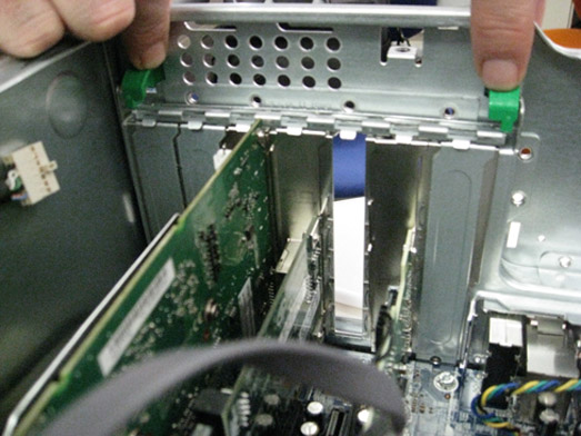
- Gently push outward on the green plastic tab, lift the defective
card straight up, and remove it from the unit.
Figure 11. Removing Graphics Card 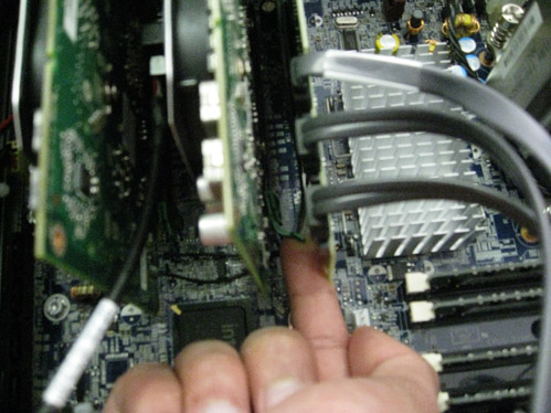
- Push down on the two green tabs to release the locking bar.
- Install the replacement graphics card into the open slot, and restore the locking bar.
- Continue to Reinstalling Host Computer in GOC.
Replacing Memory Module
Procedure
- Gently push out and down on the socket levers on the slot that
contains the faulty memory module.
Figure 12. Socket Lever Locations 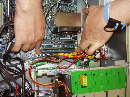
- Lift the memory module straight up, and remove it from the slot.
Figure 13. Removing Memory Module 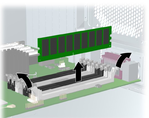
Replacing DVD Drive
Procedure
Remove the front PC cover by gently unsnapping the plastic locks located on the right side, and gently pulling on the right side of the cover.Notice Note:Ensure the cover is only pulled out far enough to disengage the locks and no further, or damage could occur to the left side tabs.
Figure 14. Front Cover Removal 
- With the right side locks disengaged, push the cover slightly
to the left while pulling out on the cover.
Figure 15. Cover Opened 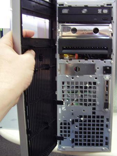
Locate and unplug the connectors for the power and data cables connected in the back of the DVD drive.Notice Figure 16. Location of Power and Data Cables 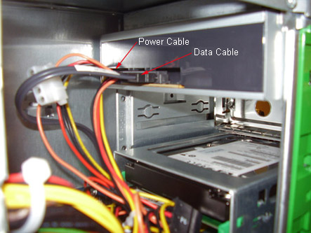
- Pull out on the plastic lock located on the left side of the
PC, and carefully remove the DVD drive.
Figure 17. DVD Drive Removal 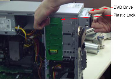
Replacing Hard Disk Drive
About this task
The procedure for removing hard drives 0 or 1 is different than the procedure for removing hard drive 2.
Replacing Hard Disk Drive 0 or 1
Procedure
- Remove the power and data cables from the hard disk drive.
Figure 18. Removing Power and Data Cables 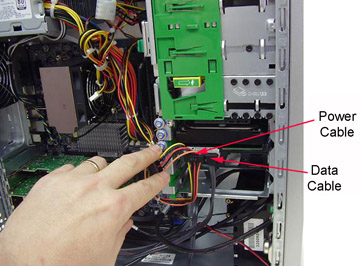
- Remove the defective hard disk by gently pulling out the plastic
tab on the left side of the drive, and extracting the hard drive as
shown.
Figure 19. Plastic Tab on Hard Drive 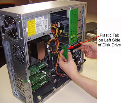
- Confirm that the data cable from all three devices are connected
to the correct SAS device locations as shown in the illustration and
table below.
Figure 20. SAS Device Locations/Data Cable Connections 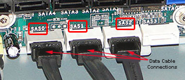
Drive Slot Drive ID SAS ID Top HDD2 SAS2 Middle HDD1 SAS1 Bottom HDD0 SAS0 - Remove and retain the four guide screws from the disk drive.
Figure 21. Guide Screws 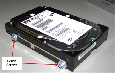
- Remove and retain the SAS HDD adapter from the hard drive.
Figure 22. SAS HDD Adapter 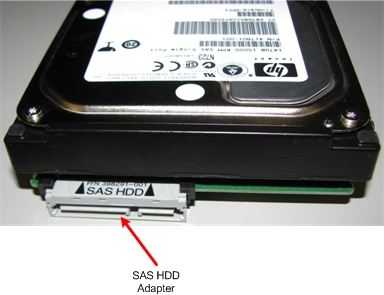
Replacing hard drive 2
Procedure
- Pull the two plastic tabs securing the front cover of the Z400
computer and gently remove the front cover.
Figure 23. Removing Front Cover 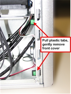
- Remove the black plastic cover from the inside of the Z400 computer.
Figure 24. Black Plastic Cover 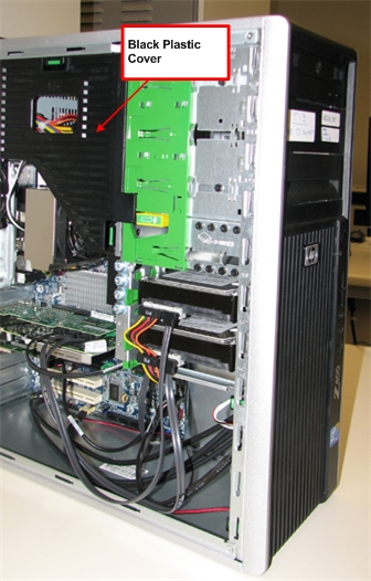
- Disconnect the power and data cables from the back of hard disk
drive 2.
Figure 25. Power and Data Cables, Plastic Clip for HDD2 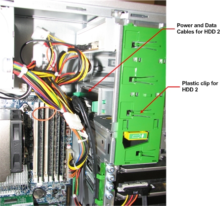
- Squeeze the two plastic tabs securing the drive in the bracket,
and push the drive out of the bracket.
Figure 26. Removing HDD2 from Bracket 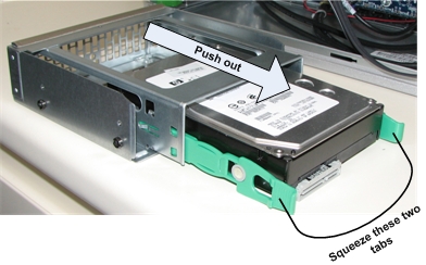
- Remove the green bracket adapter from the hard drive by gently
bending it so that the pins on the adapter come out of the screw holes
on the disk drive.
Figure 27. Bracket Adapter 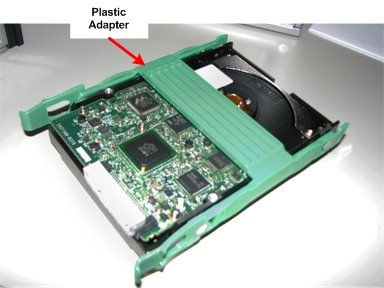
- Remove and retain the SAS HDD adapter from the hard drive.
Figure 28. SAS HDD Adapter - Carefully reinstall the front cover onto the Z400 computer.
Make sure the cover tabs align with their holes in the Z400 chassis.
It is easier to install the front cover if you align the tabs on the
cover with the chassis as shown in the following illustration.
Figure 29. Installing Z400 Front Cover 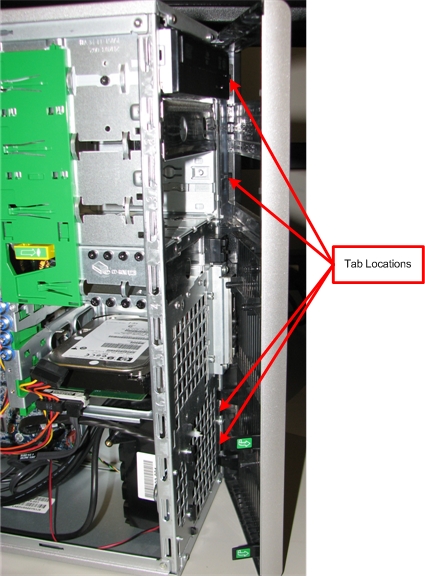
- Confirm that the data cable from all three devices are connected
to the correct SAS device locations as shown in the illustration and
table below.
Figure 30. SAS Device Locations/Data Cable Connections Drive Slot Drive ID SAS ID Top HDD2 SAS2 Middle HDD1 SAS1 Bottom HDD0 SAS0
Reinstalling Host Computer in GOC
Procedure
Powering On Operator Console
Procedure
- Remove LOTO.
- Power ON the GOC at the rear of the GOC and then power up the host PC.
-
IF THE CMOS BATTERY WAS REPLACED, press F10 as soon as the hp invent screen
appears. Setup displays at the lower right of
the screen. Perform the following steps:
- At the language prompt, leave the setting on English or use the arrows to select the language. Press Enter to confirm.
- Set the time and date. Use the Tab key to move the cursor and use the left and right arrow keys to change values.
- At the File menu, use the down arrow to highlight Save Changes and Exit and press Enter.
Finalization
Procedure
- Reboot and ensure that no memory BIOS errors appear during the boot process.
- (For DVD drive replacement) Insert media into the new DVD drive, and verify proper operation of the drive.
- (For hard disk drive replacement) Perform the applicable Loading Host System Software procedure to load software and applications onto the operating system.
- Run a goodbye scan (check scan).
- Verify that all customer functions are operational (auto voice, filming, network, archive).
- Reinstall the console front and rear covers.
- (For DV25 software or later) Computer hardware replacement may cause a change in the 16-character service license ID code. Renew any site license softkeys that were affected by the hardware replacement.