Important: The safety analyzer must be located as far away from the magnet as possible to successfully execute this test. Getting closer to the magnet affects the safety analyzer and alters the tool’s ability to take an accurate measurement.
Procedure
Plug the analyzer into a power source which allows access to the rear end of patient table.
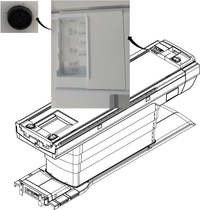
At the patient monitor accessory panel, connect the patient lead cable and the cardiac lead set at the ECG connector.
Figure 1. ECG connector
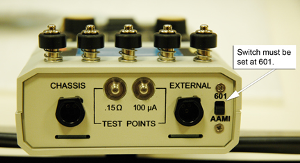
Verify that the test load selector switch is set at 601 for IEC601.1.
Figure 2. Test load selector switch setting
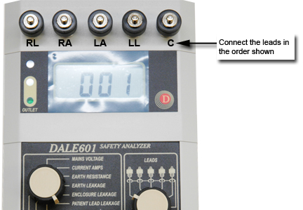
Connect the ECG leads to the Dale 601/601E [not all systems have the Cardiac {C} lead].
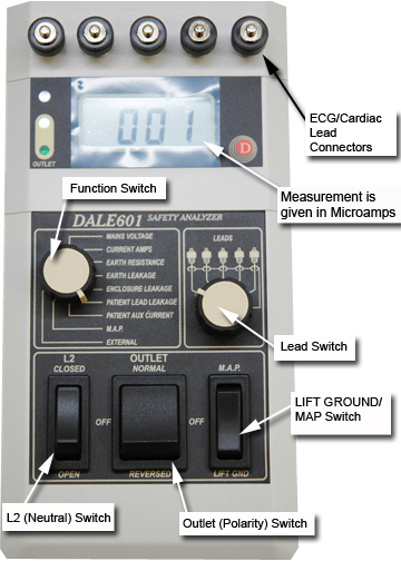
Place the L2 (Neutral) switch in the CLOSED position.
Figure 4. Dale 601/601E Safety Analyzer
Note: Be sure to pause in the OFF (middle) position when switching polarity from normal to reverse.
Place the Outlet (Polarity) switch in the NORMAL position.
On the Dale 601/601E, set the Function switch to PATIENT LEAD LEAKAGE.
Move the lead switch through the lead positions shown in Table 1. Verify that the leakage current displayed on the meter is less than 50 microamps and record the values on the data sheet.
Note: Typically, the Patient Lead Leakage (lead-to-ground) and the Patient Aux Current (lead-to-lead) readings are close to zero and less than 50 microamps. Measurements exceeding 50 microamps indicate an issue in the corresponding lead.
Table 1. Lead Positions
Lead select position
RL
RA
LA
LL
On the Dale 601/601E, set the main selector switch to PATIENT AUX CURRENT.
Move the lead switch through the lead positions shown in Table 1. Verify that the leakage current displayed on the meter is less than 50 microamps and record the values in the data sheet.
On the Dale 601/601E, set the main selector switch to M.A.P. (Mains on Applied Parts sink current).
Make sure that the leads are not touching the floor.
Move the lead switch to measure All Leads, which is the sixth position all the way to right on the switch.
On the LIFT/Ground/MAP switch, press and hold M.A.P. Make sure the leakage current displayed on the meter is less than 50 microamps and record the values on the data sheet.
Note: Be sure to pause in the OFF (middle) position when switching polarity from normal to reverse.
Repeat steps Step 7 - Step 14 with the polarity switch in the REVERSED position.