
- SIGNA™ Hero 3.0T Service Methods
- 5852800-8EN Revision 1.0
- 00000018WIA30DBFE20GYZ
- id_131064073.3
- Sep 3, 2021 10:14:05 AM
Ground Resistance Checks
Prerequisites
| Required persons | Preliminary requirements | Procedure | Finalization |
|---|---|---|---|
| 1 | Not Applicable | 60 minutes | 5 minutes |
| Item | Quantity | Effectivity | Part number | Manufacturer |
|---|---|---|---|---|
| Digital voltmeter (optional) | 1 | - | - | - |
| Bio-design MG5 meter (Microguard) with Milliohm Adapter | 1 | - |
46-194427P16 | - |
| Dale 600 or 601 (120VAC) or Dale 600E or 601E (220VAC) Safety Analyzer | 1 | - |
600/601: 46-285647P1 or 46-328406G1 600E/601E: 46-285647P14 or 46-328406G2 | - |
| Fluke ESA612 Electrical Safety Analyzer | 1 | - |
5453348-2 (220v) | - |
| Personal Lock | 2 | - |
46-194427P320 | - |
| Red Warning LOTO Tag | 2 | - |
46-194427P322 | - |
| Multi-locking Device (If multiple service people) | 1 | - |
46-194427P313 | - |
| Item | Quantity | Effectivity | Part number | Manufacturer |
|---|---|---|---|---|
| Ground Wires | as needed | - | - | - |
| ||||||||
| Condition | Reference | Effectivity |
|---|---|---|
|
Any required electrical code inspection | - | - |
|
Installation of the facility disconnect device | - | - |
|
EMERGENCY OFF wiring | - | - |
|
PDU primary wiring | - | - |
|
PDU subsystem power cables | - | - |
|
The Power Cable and Ground Cable connection. Refer to Cable Routing and Power/Ground Line Connection . | - | - |
|
No hard wired signal cables connected to any subsystem cabinets. Fiber Optic cables may be connected and not impact this check. | - | - |
About this task
This document contains a method for measuring Ground Resistance using different brands of Safety Analyzers. Only one of the Safety Analyzers listed in Tools and Test Equipment is required for this procedure.
Ground Resistance Checks are required on every site. Ground Leakage Test is only performed when local regulation or code requires it.
Ground Resistance Checks are required for the following cabinets.
-
ISC GND - Host GOC Cabinet (Performed after Power and Ground cable connection)
-
ISC GND - ICC (Performed after Power and Ground cable connection)
Review and understand the Required Conditions before beginning this procedure.
| If you are using | Go to Section |
| Microguard | Ground Resistance Checks Using Microguard |
| Dale 600/600E or 601/601E Safety Analyzer | Ground Resistance Checks Using Dale (For Those sites equipped with a Dale 600, 600E, 601, or 601E Safety Analyzer) |
| Fluke ESA612 Safety Analyzer | Ground Resistance Checks Using Fluke ESA612 |
Ground Resistance Checks Using Microguard
Procedure
Ensure that no power is applied to the Main Disconnect Panel (MDP) (see and LOTO for the Main Disconnect Panel (MDP)).DANGER 
- Plug the milliohm adaptor module into the power outlet of the Microguard.
Figure 1. Microguard Connections 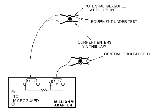 Note: Since the Microguard is being used solely as a voltmeter in this application, any other meter capable of resolving 0.1 millivolts can be substituted in the next step. Meters other than the Microguard are currently in use. Refer to the appropriate tool catalog for further information.
 - Attach the Kelvin leads. Connect one lead to the PDU ground located on ISC and the other lead to the frame of the subsystem cabinet under test.
Figure 2. ISC Ground Stud (Central Ground) 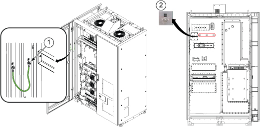
1 Ground Point for Equipment Room Measurement 2 Ground Point for Magnet Room Measurement Table 7. Equipment to be tested Equipment to be tested Host GOC Cabinet ICC (Integrated Cooling Cabinet)
Ground Resistance Checks Using Dale (For Those sites equipped with a Dale 600, 600E, 601, or 601E Safety Analyzer)
Procedure
Ensure that no power is applied to the MDP (see LOTO for the Main Disconnect Panel ).DANGER - Connect one clamp-type lead to the EXTERNAL jack on the top of the Dale safety analyzer. Connect the other clamp-type lead to the CHASSIS jack on the top of the Dale safety analyzer.
Figure 3. Top of Dale Safety Analyzer 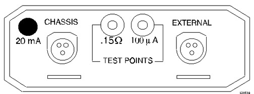
- On the Dale safety analyzer, set the main selector switch to W - RESISTANCE.
Figure 4. Dale Safety Analyzer 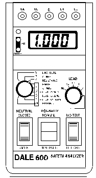
- Plug the Dale safety analyzer into an AC outlet.
Figure 5. Dale Safety Analyzer Connections 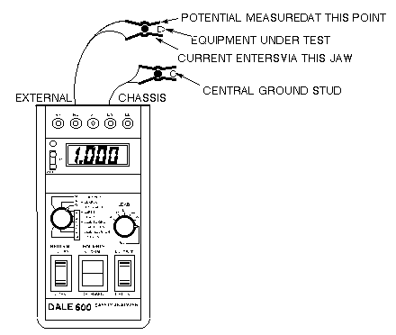 Note: The Dale safety analyzer reads resistance in ohms. For example, a reading of 0.50 equals 500 milliohms.
 - Attach the leads. Connect one lead to the PDU ground located on the ISC and the other lead to the bare frame of the subsystem cabinet under test.
Figure 6. ISC Ground Stud (Central Ground) 1 Ground Point for Equipment Room Measurement 2 Ground Point for Magnet Room Measurement Table 8. Equipment to be tested Equipment to be tested Host GOC Cabinet ICC (Integrated Cooling Cabinet)
Ground Resistance Checks Using Fluke ESA612
Procedure
Ensure that no power is applied to the MDP (see and LOTO for the Main Disconnect Panel ).DANGER - Turn on the Fluke meter and select the point to point option on the meter.
Figure 7. Fluke ESA612 Safety Analyzer 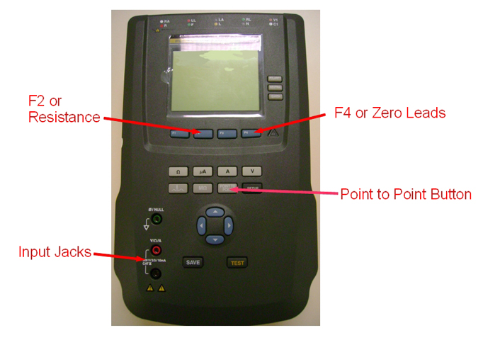
- Connect one lead to the PDU ground located on the Penetration panel of ISC and the other lead to the bare frame of the subsystem cabinet under test.
Figure 8. ISC Ground Stud (Central Ground) 1 Ground Point for Equipment Room Measurement 2 Ground Point for Magnet Room Measurement Table 9. Equipment to be tested Equipment to be tested Host GOC Cabinet ICC (Integrated Cooling Cabinet)
Finalization
Finalization
No finalization steps.