
- SIGNA™ Hero 3.0T Service Methods
- 5852800-8EN Revision 1.0
- 00000018WIA30A0D630GYZ
- id_193266203.33
- Jan 26, 2022 4:46:00 PM
Cable routing and power/ground line connection
Prerequisites
| Personnel requirements | |||
|---|---|---|---|
| Required persons | Preliminary requirements | Procedure | Finalization |
| 2 | - | 6 hours | - |
Integrated System Cabinet (ISC) PDU input voltage selection
About this task
If three-phase WYE with neutral and ground (five-wire system) input is used, the neutral must be terminated inside the main disconnect control and not brought to the system cabinet.
Procedure
- Before connecting the input power cables, determine the nominal value of the input voltage. The PDU allows for nominal input voltage of 380, 400, 415, and 480 VAC (three phase). For each three phases, be sure the wire is connected to the proper terminal for actual input voltage at the site and that the terminal screw is tight to make a good connection. For removal and installation of cable, refer to Figure 2.
Figure 1. Terminal 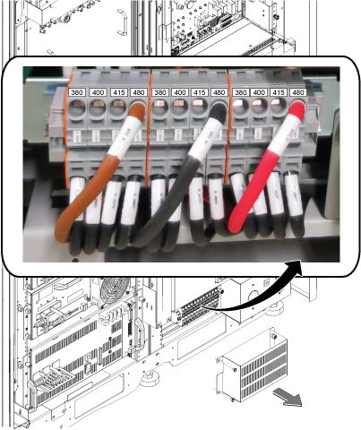 Note: For removal and installation of cable, see Figure 2.
Figure 2. How to remove/install terminal cable 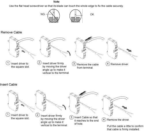 Note: When removing or inserting cable, be careful not to insert the driver to the bottom terminal slot. It may cause the equipment damage if the cable connection of the terminal is loose.
Figure 3. Notice for removing and inserting cable 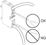
- Pull all the cables at the terminal and make sure the cables are firmly connected to the terminal.
Figure 4. Cable connection check 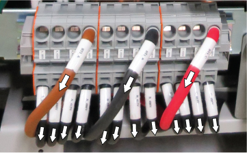
- Set the overload and short circuit trip dip SW to the correct value corresponding to the input voltage.
Figure 5. DIP SW 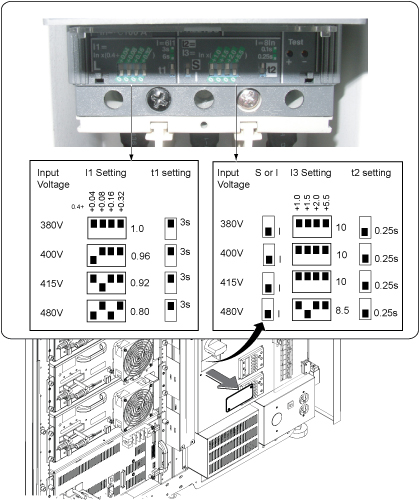
General recommendations for cable routing
About this task
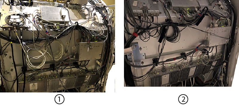
| 1 | Poor/incorrect cable routing |
| 2 | Good/correct cable routing |
- Maintain consistency in cable routing from system to system.
- The minimum bend radius of any cable must not be violated. Refer to the cable specifications.
- Excess cable should be stored.
- Excess data cables should be stored in overhead cable trays or next to the closest penetration panel in a figure-eight pattern. For small figure-eight patterns, dress and tie-wrap middle of looped cables. For longer figure-eight patterns, dress and tie-wrap ends of looped cables.
- Excess fiber optic data cable to be stored in overhead cable trays, penetration panel closet, or in magnet enclosure area must be routed in a circular pattern.
- The 600V power cables should be routed in a separate section of the cable trays away from RF and below 300V cables.
Sorting and routing cables
About this task
| Notice | |
|---|---|
Procedure
- Align the cables according to Figure 8 or Figure 9.Note: Routing for signal cables and power/ground cable is completed even though signal cable connection is not done in this section.Note: IRD cable run P5006 (8775004-11) is not pre-attached to the magnet. It is packaged separately.
Figure 7. Cable routing in scan room 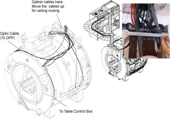
Figure 8. Scan room cable tray cross-section view for standard (on the wall) siting configuration 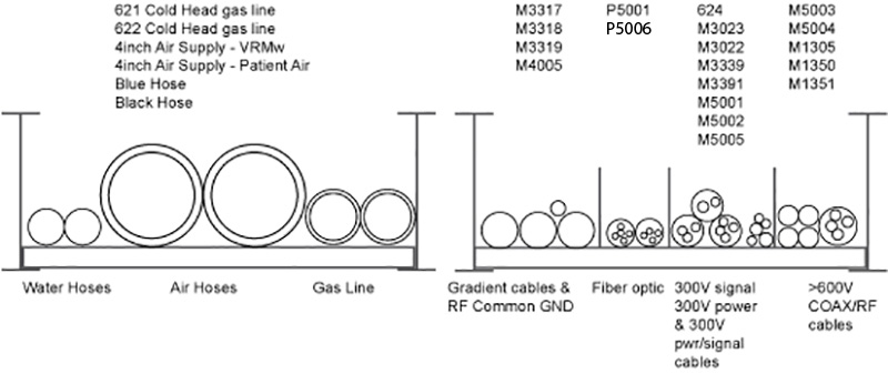
Figure 9. Scan room cable tray cross-section view for remote (off the wall) siting configuration 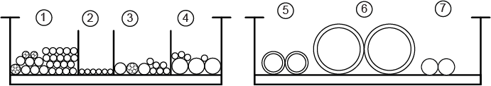
Item Description Run Number 1 300V signal, 300V power, and 300 V power/signal M3314, M3311, M3313, M3315, M5001, M3023, M3022, M3391, M3379, M3300, M3339, 1265, 1502, M3030, M0011 2 Fiber optic P5001, P5006 3 >= 600V coax/RF and AC power M5003, M5004, M1500, M1504 4 Gradient and RF and AC power M3317, M3318, M3319, M4005 5 Gas Lines (2) Run 621 cold head gas line Run 622 cold head gas line
6 Air Hoses (4) 4 inch air supply (body coil) 4 inch air supply (patent air)
4 inch air return (body coil)
4 inch air return (patent air)
7 Water Hoses (2) Blue water hose Black water hose
Note: * indicates optional cable
- Remove four pre-attached cable brackets.
Figure 10. Pre-attached cable brackets (UA magnet) 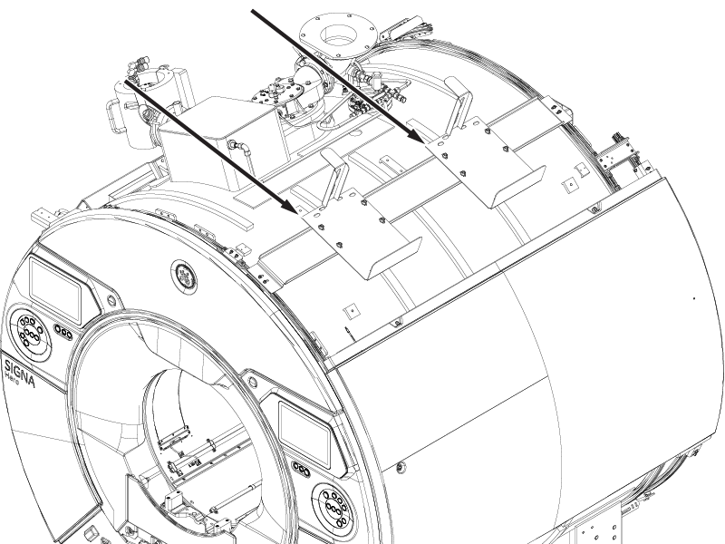
Figure 11. Pre-attached cable brackets (AR magnet) 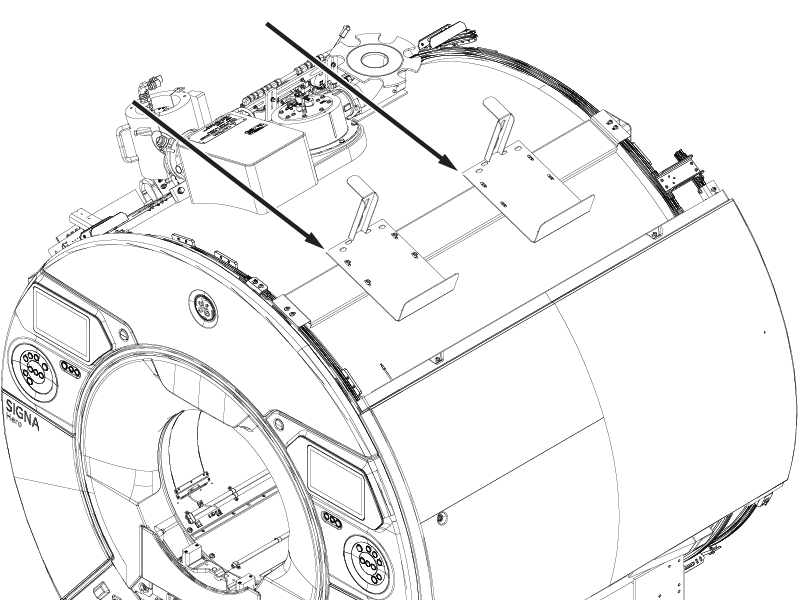
- Before routing, make sure that the cable routing does not to prevent the hoist location.
Figure 12. Cable routing above cabinets 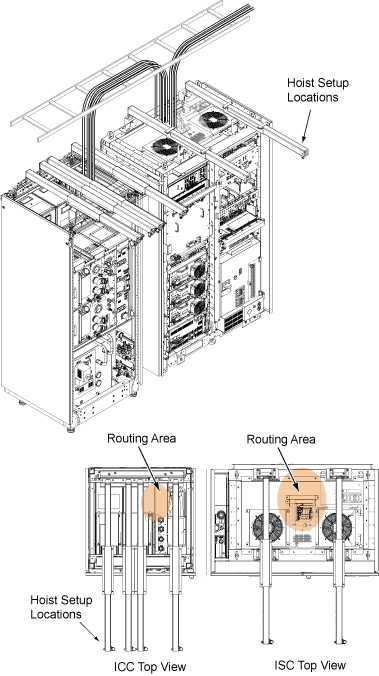
- Route the cables on cable tray in equipment room and operator room in accordance with the applicable system interconnect diagram. Align the cable according to Figure 13.Note: Routing for signal cables and power/ground cable is completed even though signal cable connection is not done in this section.
Figure 13. Cable routing in equipment room and operator room 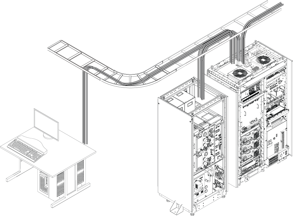
Cables from GOC to ISC/ICC for standard (on the wall) siting configuration
E5001 Harness (To ISC Cabinet IF)
E0003 (To ISC T3 Terminal)
E5002 Harness (To ICC PW)
E3503 (To ICC PW J118)
P5006 Harness (To ISC Waveguide)
Patient Alert Tube (Via ICC PW to Patient Table)
Cables from GOC to ISC/ICC for remote (off the wall) siting configuration
E5001 Harness (To ISC Cabinet IF)
E0003 (To ISC T3 Terminal)
Following cables from GOC to penetration panel for remote (off the wall) siting configuration
E5002 Harness (To PP)
E3503 (To PP J118)
P5006 Harness (To PP Waveguide)
Patient Alert Tube (Via PP to Patient Table)
Figure 14. Equipment room cable tray cross-section view for standard (on the wall) siting configuration Note: E850 is the cable between F-50SH and MM4.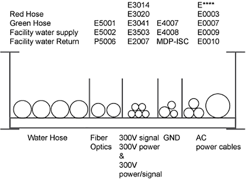
Figure 15. Equipment room cable tray cross-section view for remote (off the wall) configuration 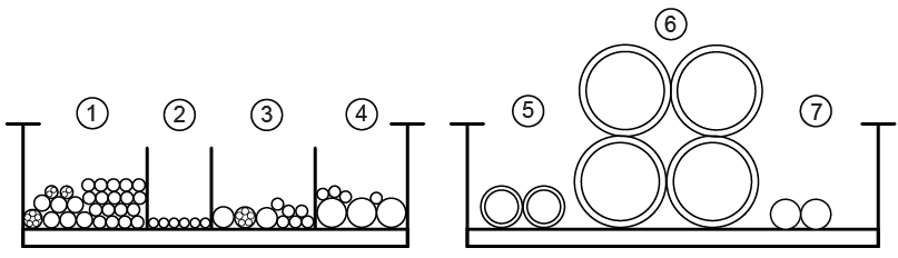
Item Description Contents 1 300V signal, 300V power, and 300 V power/signal E3311, E3313, E3314, E3315, E3360, E3302, E3303, E3391, E3324, E3379, E3300, E3534, E3532, E3533, E3316, E3031, E3023, E3022, E3030, E0011, E2018, E2019, 1265, 1502, E3014, E5001, E3020, E3040, E0010 Note: 1266 and 1501 are for oxygen monitor and Remote MRU (Optional).
2 Fiber optic E5002, P5001, P5006 3 >= 600V coax/RF and AC power E1001, E1002, E1051, E1302, E1303, E0011, E0009, E0003, E0007 4 Gradient and RF and AC power E3317, E3318, E3319, E4005 Note: The customer will provide the Ground Cable of MDP – ISC.
5 Gas Lines (2) Run 621 cold head gas line Run 622 cold head gas line
6 Air Hoses (2) 4-inch air supply (body coil) 4-inch air supply (patent air)
4-inch air return (body coil)
4-inch air return (patent air)
7 Water Hoses (2) Blue water hose Black water hose
Note: * indicates optional cable
- Plan for storage location of coiled cable excess length if cables are to remain at delivered length.
For fiber optic cables, see the notice above to ensure the cables are not damaged.
For non-fiber optic cables, store the cables as shown.
Figure 16. Proper storage of excess cables 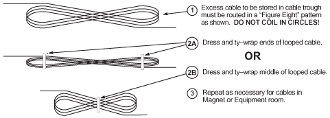
Power and ground cable connection
System cabinet power cable connection
About this task
On the main power cable, strip the cable covering material according to Figure 18.
Procedure
- Install rear cable duct.
Figure 17. Install rear cable duct 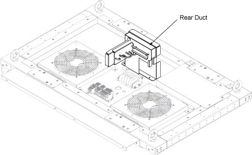
- Connect power cables to ISC top terminal.Note: Top covers will be installed after signal cable wiring. Leave the top covers removed during ground resistance check.
Figure 18. Power cable and ground cable connection 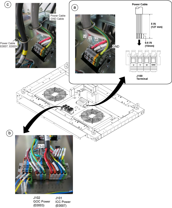
ICC power cable connection
Procedure
- Connect E0007 and GND cables according to the following illustration.
Figure 19. ICC power and ground cable wiring 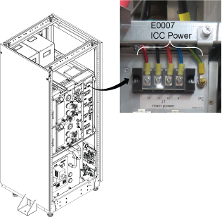
GOC power cable connection
Procedure
- Connect E0003 according to the following step.
- Remove two screws and remove cable fixing plate.
- Loosen two screws and remove plug cover by pulling up a little.
- Connect E0003 cable.
- Restore the plug cover and cable fixing plate in reverse order of removal.
Figure 20. GOC E0003 cable 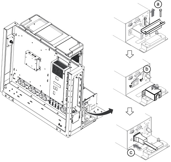
Connection of magnet ground, Run M4005 for standard (on the wall) siting configuration
Procedure
- Connect Run M4005 to the ground stud of ISC (scan room side). The other end is pre-connected to the magnet ground stud.
Figure 21. Ground studs location 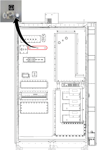
- Connect the other end of Run M4005 to the ground point of magnet.
Figure 22. Ground point of magnet 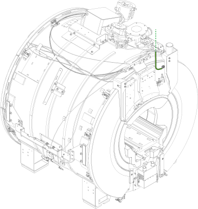
Finalization
Connection of penetration panel ground and magnet ground for remote (off the wall) siting configuration
Procedure
- Connect another side of Run E4005 to the ground stud Pen Panel (Equipment room side). See Figure 23.
Figure 23. Ground stud of Pen Panel 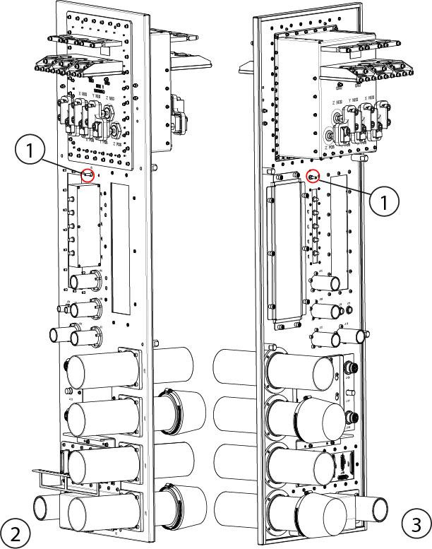
Item Description 1 Ground stud 2 Equipment room 3 Scan room