- Discovery MR750 3.0T System Service Methods
- 5690009-2EN Revision 4
- 00000018WIA300C6410GYZ
- id_20044477.0
- Feb 22, 2021 2:30:11 AM
Using Dale 601/601E Safety Analyzer
About this task
Important: The safety analyzer must be located as far away from the magnet as possible to successfully execute this test. Getting closer to the magnet affects the safety analyzer and alters the tool’s ability to take an accurate measurement.
Procedure
-
Plug the analyzer into a power source in the magnet room which allows access to the patient monitor accessory hook on the left side of the magnet enclosure, while staying at least 20 inches (51 cm) from the magnet.
The patient monitor accessory hook is on the left side of the magnet, regardless of system version. The example shown below is an MR450 system.
Figure 1. Patient monitor accessory hook location (example) 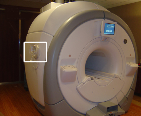
- At the patient monitor accessory panel, connect the patient lead cable and the cardiac lead set at the ECG connector.
The ECG connector is round and is labeled with ECG or a heart symbol. The example shown below is an MR450w system.
Figure 2. ECG connector (Example) 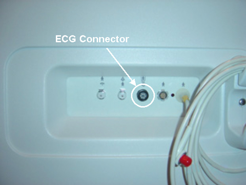
- Verify that the test load selector switch is set at 601 for IEC601.1.
Figure 3. Test load selector switch setting 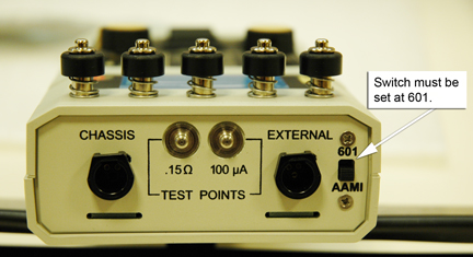
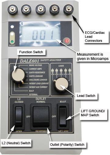
- Connect the ECG leads to the Dale 601/601E [not all systems have the Cardiac {C} lead].
Figure 4. Dale 601/601E Analyzer: connecting leads 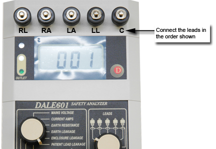
- Place the L2 (Neutral) switch in the CLOSED position.
Figure 5. Dale 601/601E Safety Analyzer