- Discovery MR750 3.0T System Service Methods
- 5690009-2EN Revision 4
- 00000018WIA30B20450GYZ
- id_20214023.1
- Nov 13, 2020 3:21:29 PM
Setting up hardware for UPM - MNS amplifier calibration or functional check
Sets up hardware for functional checks or calibration of forward power for the Universal Power Monitor (UPM) and Multi-Nuclear Spectroscopy (MNS) amplifier.
Procedure
- Inhibit TR faults. Disable the driver module TR fault detection in the PEN cabinet. Make sure that switch SW2 is in the TR DISABLE position.
Figure 1. Driver module front switches 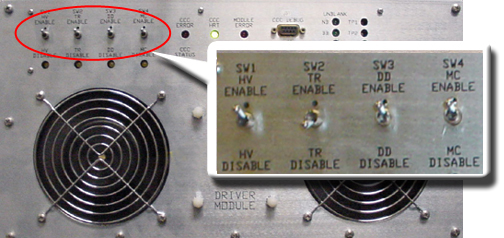
- Set RF Enable S2 on the MNS exciter to Disable (down).
Figure 2. MNS exciter RF enable S2 switch location in disable (down) 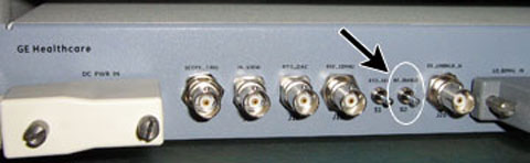
- Remove the transmission cable from RF OUT.
- (For AMT amplifier) Remove cable from J4.
- (For the GEN 1 CPC amplifier) (5411744) Remove cable from J3.
- (For the GEN 2 CPC amplifier) (5750811) Remove cable from J2.
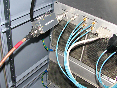
Connect directly to the 35 kW 3.0T RF dummy load. Plug the power supply into the dummy load and the power supply into the 110 VAC service outlet in the cabinet.
Figure 3. Setup for MNS output measurement 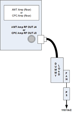
Figure 4. Coupler attached to J3 on combiner 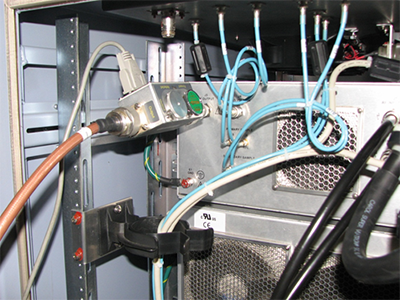
Figure 5. Coupler attached to J2 on power amplifier