
- Discovery MR750 3.0T System Service Methods
- 5690009-2EN Revision 4
- 00000018WIA3023D030GYZ
- id_123740021.15
- Oct 11, 2021 3:47:40 PM
Replacing CPC MNS amplifier components
Describes the replacement procedures for the major components of the CPC cabinet.
Prerequisites
| Personnel requirements | |||
|---|---|---|---|
| Required persons | Preliminary requirements | Procedure | Finalization |
| 1 | - | 120 minutes | 20 minutes |
| Tools and test equipment | |||
|---|---|---|---|
| Item | Quantity | Part number | Manufacturer |
| Hoist Service Kit | 1 | 5196226 | - |
| Hoist Beam Adapter Bracket | 1 | 5750811-13 | - |
| Replacement parts | |||
|---|---|---|---|
| Item | Quantity | Part number | Manufacturer |
| DV Combiner FRU Collector (Top), Gen1 | 1 | 5411744-8 | - |
| DV Power Amplifier FRU Collector, Power Amplifiers #1 and #2, Gen1 | 1 each | 5411744-6 | - |
| DV Driver Amplifier FRU Collector, Gen1 | 1 | 5411744-7 | - |
| DV Master Power Supply FRU Collector (Bottom), Gen1 | 1 | 5411744-9 | - |
| 3T MNS RF Amplifier (Power Amplifier), Gen2 | 1 | 5750811-8 | - |
| 3T MNS RF Amplifier (Power Supply), Gen2 | 1 | 5750811-7 | - |
| Safety | ||||||||||||
|---|---|---|---|---|---|---|---|---|---|---|---|---|
|
Before working in any GE Healthcare MR suite or performing any GE Healthcare service procedure, you must:
If you have any safety concerns at any time, do not begin work or immediately stop work and move to a safe location. Immediately contact your supervisor or site safety officer for instructions on how to proceed. | ||||||||||||
| ||||||||||||
The document describes the replacement procedures for the major components of the original Gen1 CPC cabinet (5411744) and the new Gen2 cabinet (5750811). Because all of the major components are the same dimensions (depth and width), the replacement instructions are the same, with the exception of the top module of the original cabinet (5411744).
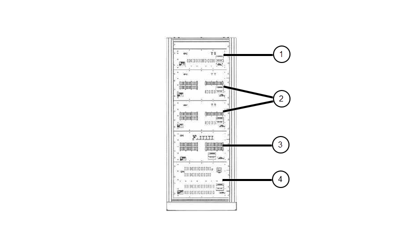
The major components of the original CPC cabinet (5411744) are:
- Combiner module: 5411744-8
- Power amplifier #1 and #2: 5411744-6
- Driver chassis: 5411744-7
- Power supply: 5411744-9
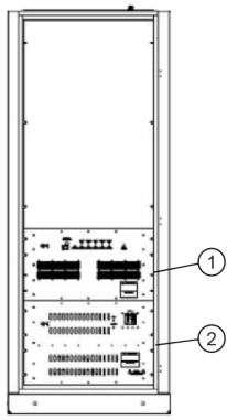
The major components of the new CPC cabinet (5750811) are:
- Power amplifier: 5750811-8
- Power supply: 5750811-7
Preparation
Procedure
- Confirm that the hoist support brackets are installed.
Figure 3. CPC Cabinet – Top with Hoist Support Brackets 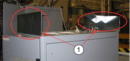
Item Description 1 Hoist support brackets
Install the hoist. Use the instructions in Hoist Service Kit and Lifting Accessories to set up the hoist.Warning Instead of the support tube (from the HEC cabinet) being attached to the top of the cabinet, the support tube is attached to the front hoist support bracket.
Figure 4. Hoist Installed on CPC Cabinet 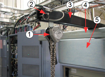
Item Description 1 Hoist pulley and chain 2 Hoist safety pin 3 Main lifting beam from PDU/PGR 4 Support tube from HEC 5 MNS Hoist support bracket
Replace Combiner
Procedure
- With two engineers, release the slide rails on both sides of the combiner. Support the combiner during this process.
Figure 5. 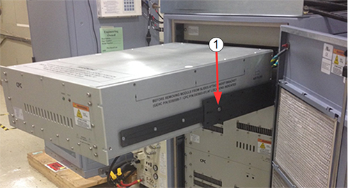
Item Description 1 Slide cabinet rail back into the cabinet while supporting weight of combiner - Attach the FRU replacement brackets to each side of the combiner module.
Each bracket is held in place with three screws. Tighten each screw so that the bracket is securely fastened to the component.
Figure 6. FRU Replacement Bracket on Component 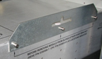
Attach the hoist hooks into the slots on each bracket.Warning When removing the top module, there will be some slack in the hoist chain. Confirm that the chain links are aligned properly.
Figure 7. Hoist Hooks Attached to Combiner Module 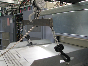
- Remove the module by having two FEs support both sides of the module, then slide the guide rail back into the cabinet.
Figure 8. Removing Module from CPC Cabinet 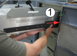
Item Description 1 Slide cabinet rail back into the cabinet while supporting weight of combiner - Lower the combiner module onto the top section of the FRU crate.
Figure 9. Top Section of FRU Packing Crate 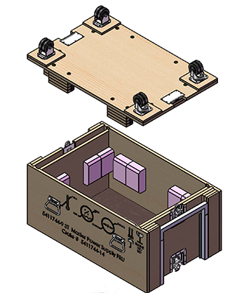
Replace Amplifier Component
About this task
The original CPC cabinet has four lower component (power amplifier #1 and #2, driver chassis, and power supply) that all have the same dimensions (depth and width). The replacement instructions for these components are the same. The new CPC cabinet has two lower components (power amplifier and power supply. They also have the same dimensions and same replacement instructions.
Procedure
- Attach the FRU replacement brackets to each side of the combiner module.
Each bracket is held in place with three screws. Tighten each screw so that the bracket is securely fastened to the component.
Figure 10. FRU Replacement Bracket on Component
Attach the hoist hooks into the slots on each bracket. Install the spreader bar to the hoist to stabilize the chains. Confirm that the chain links are aligned properly.Warning Figure 11. Spreader Bar Attached to Hoist 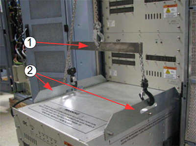
Item Description 1 Hoist spreader bar 2 FRU replacement brackets - Retract the guide rails from each side. Push in the button on the guide rail to unlock the rail and slide the rail back into the cabinet.
The hoist is now supporting the component.
Figure 12. Release Button on Guide Rail 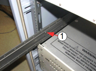
Item Description 1 Button on cabinet guide rail - Lower the component onto the top section of the FRU crate. Move the defective component out of the way and move the new component into position.
Figure 13. Top Section of FRU Packing Crate
Finalization
Finalization
-
Return the FRU replacement brackets with the failed component.
-
Repack the hoist service kit. See Hoist Service Kit and Lifting Accessories.
-
Remove LOTO from the RF amplifier. See MR Service Safety Manual, PN 5452735.
-
Run: