- Discovery MR750w and SIGNA™ Architect T 3.0T System Service Methods
- 5690002-2EN Revision 4
- 00000018WIA30E2F030GYZ
- id_123738681.20
- Feb 7, 2022 4:46:42 PM
LPCA Cable Tracks Replacement
Prerequisites
| Required persons | Preliminary requirements | Procedure | Finalization |
|---|---|---|---|
| 1 | Not Applicable | 90 minutes | 30 minutes |
| Item | Quantity | Effectivity | Part number | Manufacturer |
|---|---|---|---|---|
| Assorted cable ties | Multiple | - | - | - |
| Non-magnetic service tool kit | 1 | - |
| - |
| MCRv tool kit | 1 | - |
5182417-2 | - |
| Item | Quantity | Effectivity | Part number | Manufacturer |
|---|---|---|---|---|
| Loctite 242 | 1 | - |
46-170686P1 | - |
| Item | Quantity | Effectivity | Part number | Manufacturer |
|---|---|---|---|---|
| A-Port legacy cable track assembly | 1 | - |
See FRU manual | - |
| GEM P1 only cable track assembly | 1 | - |
See FRU manual | - |
| P1 only cable track assembly, 3.0T | 1 | - |
See FRU manual | - |
| Safety |
|---|
|
Before working in any GE Healthcare MR suite or performing any GE Healthcare service procedure, you must:
If you have any safety concerns at any time, do not begin work or immediately stop work and move to a safe location. Immediately contact your supervisor or site safety officer for instructions on how to proceed. |
| Warning | |
|---|---|
About this task
Overview
The LPCA of 32–channel systems contains two independent tracks. This procedure describes the replacement of either LPCA cable track. The tracks are FRU assemblies, meaning if one or more cables within a track fails, the entire track is replaced. Each track contains different cables, and each track has different connector types at both ends. Because of these differences, the procedure for replacing one cable track differs from the procedure for replacing the other cable track.
As viewed from the front of the magnet, the P1 coil connectors track is on the left side of the rear pedestal and is designated by three FRUs noted in Replacement Parts. (See Table 5 for all RRx receive chain cable types.) The A-port and other associated cable tracks are located on the right side of the rear pedestal (see Table 6 for all cable types).
Remove Cable Track
Procedure
- Remove the LPCA cover.
Figure 1. LPCA Cover Screw Locations 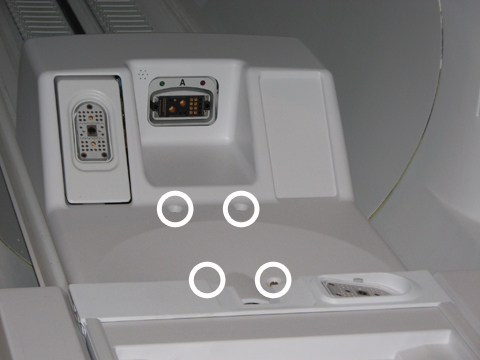
- Remove the P1 and/or P2 quick release modules. Use sufficient force to pull the module forward to slide it off the track.
Figure 2. Remove the Quick Release Module 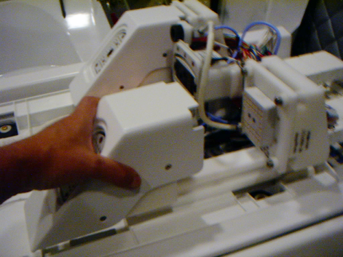
- To create enough space to remove and replace P1/P2 cable connectors, do the following:
- At the rear of each cable mount bracket, remove two screws from the left side and three screws from the right side, and then set the cable connector aside.
Figure 3. Cable Connector Screws 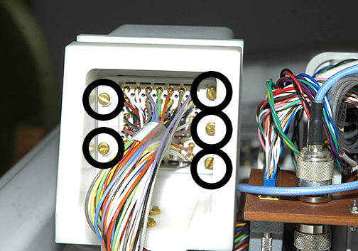
Figure 4. Cable Mount Bracket Screws 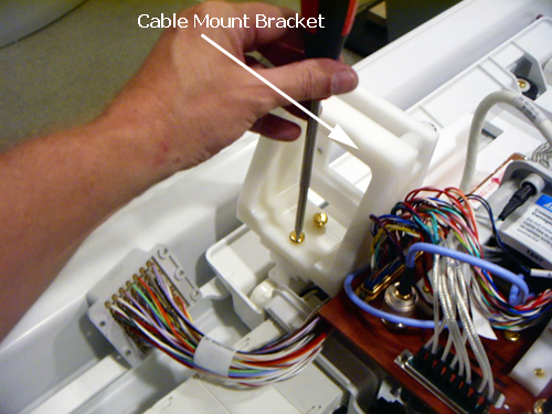
- At the rear of each cable mount bracket, remove two screws from the left side and three screws from the right side, and then set the cable connector aside.
- Remove four slotted brass screws from the front and back of the balun.
Figure 5. Balun 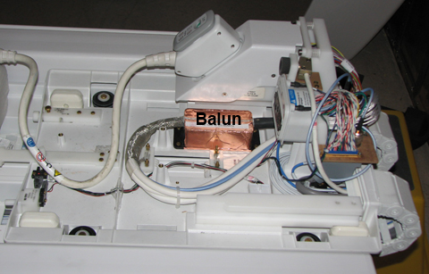
- Remove the two slotted head brass screws that secure the cable track lead to the base of the LPCA.
Figure 6. Cable Track Lead Screw Locations 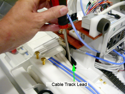
- Remove the two slotted head screws that secure the cable track lead to the front of the rear pedestal bridge.
Figure 7. Bridge Cable Track Screw Locations 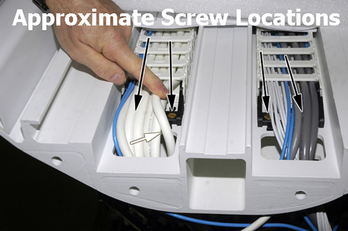
- Feed loose end of cable connections up through the opening at the front of the rear pedestal bridge and let them lay freely on the bridge.
Figure 8. Cable Track Opening in Bridge 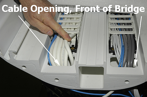
- Starting from the front of the LPCA, pull the cable track (the side that includes the baluns) through the opening on the LPCA in a forward direction.
Figure 9. Removal Path of P1/P2 Cable Track 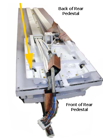
Removal of A-Port Connector Cable Track
Procedure
- Remove four slotted brass screws from top of LPCA bulkhead plate. Carefully move wires out of the way when removing screws.
Figure 10. Top of Bulkhead Plate 
- Remove the two slotted head brass screws that secure the cable track lead to the base of the LPCA.
Figure 11. Cable Track Lead Screws 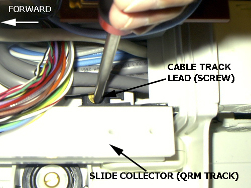
Installation of New Cable Track
Procedure
- To ensure proper installation and reconnection of cables, reverse the Removal procedures above (Step 16 or Remove Cable Track).Note: Wire tie the cables out of the way of the quick release module and slide mounting. The quick release module must slide freely without interference.
Figure 12. Proper Cable Routing 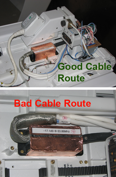
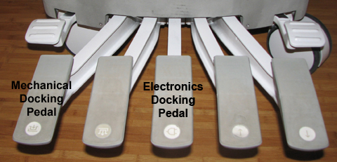
- Dock the patient table to drive the LPCA to the home position and reattach it to the cradle/patient table. Be sure to dock the electronics on 32-channel systems by pressing the foot pedal.
Figure 13. Electronics Docking Pedal