Basic Service Documentation. Copyright General Electric Company.
Object ID: 00000018WIA304CFF20GYZ
Topic ID: id_13106114 Version: 1.2
Date: Jul 5, 2019 10:46:04 PM
Motor On Switch Actuation Adjustment
Prerequisites
Table 1. Personnel requirements
Required persons
Preliminary requirements
Procedure
Finalization
1
-
-
-
Table 2. Safety
Warning
FERROUS MATERIAL HAZARD!!
THE DOCK ASSEMBLY MAIN DOCK COVER CONTAINS A MOTOR MADE
WITH FERROUS COMPONENTS. HOLDING THIS ASSEMBLY TOO CLOSE TO THE MAGNET
BORE WILL CAUSE IT TO BE FORCIBLY ATTRACTED TO THE MAGNET.
TO PREVENT POSSIBLE BODILY INJURY OR DAMAGE TO MOTOR, MAGNET
ENCLOSURE, OR MAGNET, PLACE DOCK ASSEMBLY ON FLOOR AND SLIDE IT OUT
OF EXAM ROOM.
About this task
The Dock Motor Speed Procedure is required as part of set-up
and calibration. Procedures for opening magnet enclosure covers and
adjusting patient dock hardware (Dock Motor Gear Assembly Adjustments) are provided
in case related Dock problems arise. The Motor On actuation switch
in the dock assembly should be adjusted so it is activated when the
Table Up foot pedal is pressed approximately 3/4 of its total length
of travel. This is factory adjusted; however, it is possible to adjust
the position of the Motor On switch in the field to maintain the proper
actuation level.
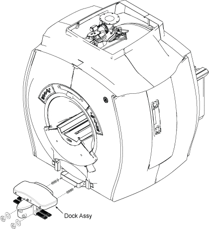
Remove dock assembly from dock support by removing capscrews,
lock washers, and clamps (Figure 1).
Figure 1. DOCK ASSEMBLY R/R
Slide dock assembly away from magnet enclosure to gain access
to cable connections.
Remove small trim plate on front enclosure skirt, just above
cutout to access dock motor power cable and Up Limit switch cable
connections (Figure 1).
Disconnect all cables from Dock Assy.
Warning
FERROUS MATERIAL HAZARD!!
THE DOCK ASSEMBLY MAIN DOCK COVER CONTAINS A MOTOR MADE
WITH FERROUS COMPONENTS. HOLDING THIS ASSEMBLY TOO CLOSE TO THE MAGNET
BORE WILL CAUSE IT TO BE FORCIBLY ATTRACTED TO THE MAGNET.
TO PREVENT POSSIBLE BODILY INJURY OR DAMAGE TO MOTOR, MAGNET
ENCLOSURE, OR MAGNET, PLACE DOCK ASSEMBLY ON FLOOR AND SLIDE IT OUT
OF EXAM ROOM.
Slide dock assembly out of scan room, observing danger precautions
above.
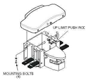
Remove four mounting bolts from main dock cover (Figure 2).
Figure 2. DOCK COVER REMOVAL
Slide main dock cover forward until Up Limit switch push rod
just clears main dock cover holes (Figure 2).
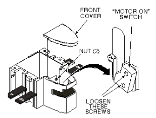
Remove front cover by removing two nuts securing front cover
to dock (Figure 3).
Figure 3. MOTOR ON SWITCH ADJUSTMENT
Loosen two mounting screws securing Motor On switch to side
of dock assembly (Figure 3 above).
Adjust Motor On switch position so it is activated (clicks)
when the Table Up foot pedal is pressed approximately 3/4 of its total
length of travel.
After adjustment is complete, tighten two mounting screws.
Reinstall front cover by attaching two mounting nuts.
Carefully position main dock cover so that Up Limit switch push
rod is aligned with upper hole in main dock cover.
Replace main dock cover by securing four mounting bolts (Figure 2).
Warning
FERROUS MATERIAL HAZARD!!
THE DOCK ASSEMBLY MAIN DOCK COVER CONTAINS A MOTOR MADE
WITH FERROUS COMPONENTS. HOLDING THIS ASSEMBLY TOO CLOSE TO THE MAGNET
BORE WILL CAUSE IT TO BE FORCIBLY ATTRACTED TO THE MAGNET.
TO PREVENT POSSIBLE BODILY INJURY OR DAMAGE TO MOTOR, MAGNET
ENCLOSURE, OR MAGNET, PLACE DOCK ASSEMBLY ON FLOOR AND SLIDE IT OUT
OF EXAM ROOM.
Slide dock assembly into scan room, observing danger precautions
noted above.
Connect cables.
Attach small trim plate on front enclosure skirt, just above
cutout (Figure 1).
Install dock assembly to magnet enclosure with attaching hardware.
Restore Power
Dock patient transport.
Ensure that dock Motor On switch operates properly when Table
Up pedal is pressed.