- SIGNA MR355 / SIGNA MR360
- Service Manual
- 5856356-3EN Revision 5.0
- Basic Service Documentation. Copyright General Electric Company.
- 00000018WIA30910030GYZ
- id_131076371.6
- Jul 5, 2019 11:49:10 PM
Gradient Coil Replacement Coil Installation
Prerequisites
| Required persons | Preliminary requirements | Procedure | Finalization |
|---|---|---|---|
| 4 minumum | - | 6 hours | - |
| Item | Quantity | Effectivity | Part number | Manufacturer |
|---|---|---|---|---|
| small carpenter's level | 1 | - | - | - |
| 12-inch length of 1/2-inch I.D. hose | 1 | - | - | - |
| 2 hose clamps for 1-inch O.D. hose | 1 | - | - | - |
| 4-inch-long piece of copper tubing, 1/2-inch O.D. | 1 | - | - | - |
| Roll of paper toweling | 1 | - | - | - |
| Pair of latex gloves | (optional) | - | - | - |
| Non-magnetic torpedo level or similar | 1 | - | - | - |
| Epoxy-filled Gradient Coil cart (2134810), cradle (2134810-2), and accessory kit (2134810-4). | 1 | - |
2144093 | - |
| Class 1 electric rider lift truck, 4-wheel, rated at 6000 lbs (in case the coil, cart, and cradle must all be lifted together— a necessity in mobiles); with forks a minimum of 56 inches long; with side shifter for easy width adjustment and lateral movement of forks. | 1 | - |
n/a | - |
| Non-magnetic tool kit | 1 | - |
46-320273G1, G2, G3, or G4 | - |
| ||||
| Condition | Reference | Effectivity |
|---|---|---|
|
Verify that the Epoxy-filled Gradient Coil accessory kit contains all the parts listed in Kit Contents. | - | - |
About this task
After having the fork lift truck remove the failed coil and cradle from the cart, the replacement body coil, on its cradle, must be loaded and taken to the scan room.
For Mobiles
About this task
The most difficult part of this procedure is getting the replacement coil correctly aligned so that it rolls easily and completely into the bore. A small carpenter's level is a useful tool to have at this point.
Procedure
-
Figure 1 shows replacement
coil and cradle loaded lengthwise on forks, with leading edge resting on wood
stack.
Figure 1. ALIGN REPLACEMENT COIL & CRADLE WITH BORE 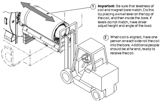
REPLACEMENT COIL INSTALLATION
Procedure
Loading Replacement Coil on CartLoading Replacement Coil/Cradle on CartCAUTION Figure 2. LOADING REPLACEMENT COIL/CRADLE ON CART 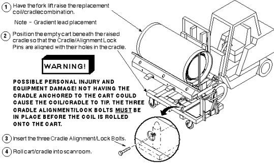
- Moving Coil into Magnet:
- Positioning Replacement Coil at Magnet
Figure 3. POSITIONING REPLACEMENT COIL AT MAGNET 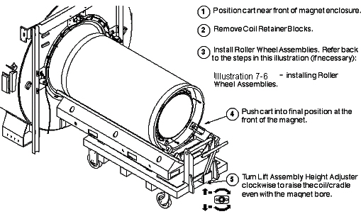
- Installing Replacement Coil
Figure 4. INSTALLING REPLACEMENT COIL 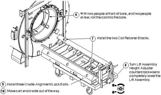
- Mounting the Roller Wheel Assemblies
Figure 5. MOUNTING THE ROLLER WHEEL ASSEMBLIES 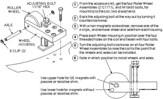
- Positioning Replacement Coil at Magnet
- Aligning the Coil in the Bore: Once the replacement coil is in the bore,
it must be aligned along the x, y, and z axes.
- Aligning the coil along the z-axis. See Figure 6 for the BRM Coil or Figure 7 for
the CRM Coil.
Figure 6. ALIGNING BRM COIL ALONG THE Z-AXIS 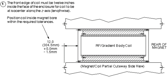
Figure 7. ALIGNING CRM COIL ALONG THE Z-AXIS 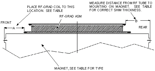
Table 5. COIL ALIGNMENT Coil Type ⇒ BRM ALL MAGNETS 1.0T AND 1.5T ONLY
CRM Magnet Type ⇒ S1 Oxford S2 S3 S4 W.B. S2 S3 S4 W.B. Magnet Length NOM. REF.
MTG Flange to MTG Flange21900.8 MM (86.25 IN)
2290.1 MM (90.16 IN)
2228.9 MM (87.75 IN)
2228.9 MM (87.75 IN)
A BRM distance to FRT Magnet Face
+0.0 285.5 MM
-1.5(11.24 IN)
+0.0 335.0 MM
-1.5(13.18 IN)
+0.0 304.5 MM
-1.5(12.00 IN)
+0.0 264.5 MM
-1.5(10.43 IN)
Front Rubber Shims Needed 22.0 MM (0.87 IN)
1.50 MM (0.6 IN)
1.50 MM (0.6 IN)
1.50 MM (0.06 IN)
B RF Tube Distance to Rear Magnet Face
Measure in MM Measure in MM Measure in MM Measure in MM Rear Rubber Shims Needed 393.0 - B MM
417.0 - B MM
393.0 - B MM
583.0 -B MM
- Aligning the coil along the x-axis
Figure 8. ALIGNING THE COIL ALONG THE X-AXIS 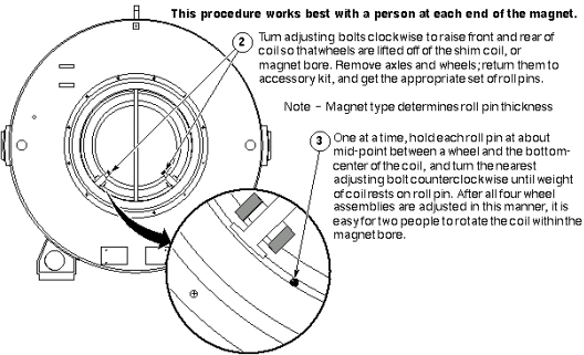
The replacement gradient coil is now completely installed. At this point, you may follow either of two procedures:
-
If the RF Body Coil was removed for later installation in the replacement gradient body coil, perform the procedure to install RF coil below in Install RF Coil,
OR
-
If the RF Body Coil was replaced along with the gradient coil, go on to the following Connecting Replacement Coil.
- Aligning the coil along the z-axis. See Figure 6 for the BRM Coil or Figure 7 for
the CRM Coil.
Install RF Coil
Procedure
- Install Tracks in Replacement Gradient Coil
Figure 9. INSTALL TRACKS IN REPLACEMENT GRADIENT COIL 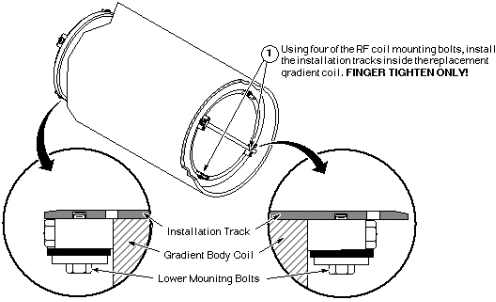
- Install RF Coil in Gradient Coil
Figure 10. INSTALL RF COIL IN GRADIENT COIL 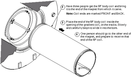
- Securing RF Coil in Gradient Coil
Figure 11. SECURING RF COIL IN GRADIENT COIL 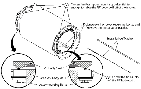
- Centering RF Coil in Gradient Coil
Figure 12. CENTERING RF COIL IN GRADIENT COIL 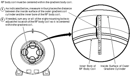
Connecting Replacement Coil
Procedure
- Reconnect Cooling Hoses, Acoustic Collar, and Power
Figure 13. RECONNECT COOLING HOSES, ACOUSTIC COLLAR, AND POWER 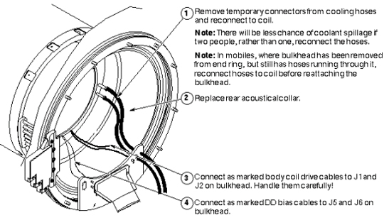
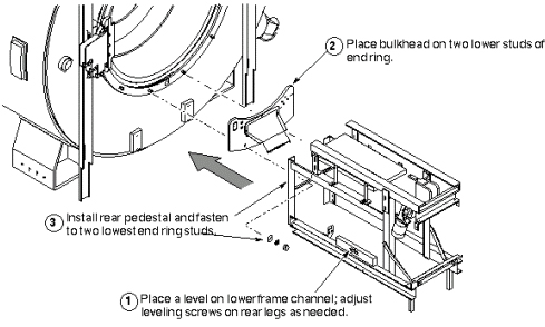
- Reinstall Rear Pedestal (in Mobiles only)
Figure 14. REINSTALL REAR PEDESTAL (IN MOBILES ONLY)