- id_13106443
- Version: 4.0
- Date: Feb 14, 2020 4:07:07 PM
MNS installation and upgrade (3.0T)
Prerequisites
| Required persons | Preliminary requirements | Procedure | Finalization |
|---|---|---|---|
| 2 | Not Applicable | 9 hours | Not Applicable |
| Item | Quantity | Effectivity | Part number | Manufacturer |
|---|---|---|---|---|
| Non-magnetic Tool Kit | 1 | - | - | - |
| Item | Quantity | Effectivity | Part number | Manufacturer |
|---|---|---|---|---|
| Tie Wraps | As needed | - | - | - |
| Item | Quantity | Effectivity | Part number | Manufacturer |
|---|---|---|---|---|
| Ferrite toroid key | 1 | - | - | - |
|
| Condition | Reference | Effectivity |
|---|---|---|
| Remove any twists and kinks from the cabling. When routing cables, avoid circular loop bundles. Use “figure eight” coils of less than 6 ft (2 m) in diameter. | - | - |
| Allow 3 ft (1 m) of cable slack at the entrance to the cabinets. | - | - |
| If the amplifier cabinet is a AMT/Herley, move the MNS cabinet door down using the adjustable hinges before positioning the cabinet. With an opening at the top of the cabinet, the cables can be routed up and out of the MNS cabinet. | - | - |
There are two individual amplifiers that are utilized for the spectroscopy option:
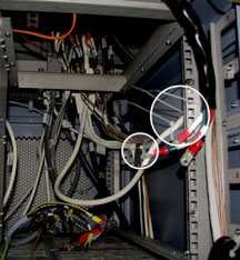
- 8 kW AMT/Herley amplifier – This is the original amplifier and is easily identified by cables connecting to the rear of the cabinet.
Figure 1. 8 kW AMT/herley cabinet – front and back
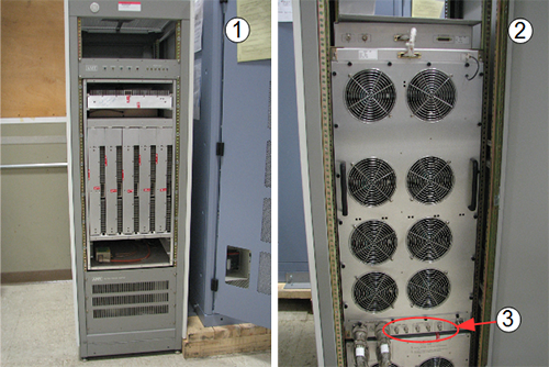
Item Description 1 Front of 8 kW AMT/Herley cabinet 2 Back of 8 kW AMT/Herley cabinet 3 Cable connections - CPC MNS amplifier – This is a new amplifier introduced in summer of 2014. Cables connect to the top of the cabinet for this amplifier.
Figure 2. CPC cabinet – front and top
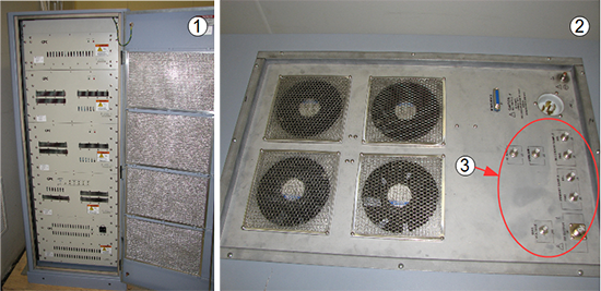
| Item | Description |
| 1 | Front of CPC cabinet |
| 2 | Top of CPC cabinet |
| 3 | Cable connections |
Two hoist support brackets are in the bottom of the CPC cabinet crate. Install them on the top of the cabinet so that they do not get lost.
Figure 3. CPC Cabinet – top with hoist support brackets
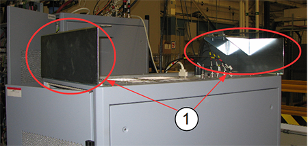
| Item | Description |
| 1 | Hoist support brackets (2) |
System power shutdown
Procedure
 danger
- notice
- To prevent fatal electric shock, disconnect the power from the PDU before doing the following procedures.
- Do LOTO on the PGR PDU/gradient subsystem, which disconnects the INPUT circuit breaker. See the MR Service Safety Manual, PN 5452735.
 |
Installing RF detector boards, BB AIF board, and cables
- Amp IF Board: a quantity of 1 BB Amp IF Board is required for the MNS option, either PN 5250032 (non-RoHS) or 6250112 (RoHS)
- RF Detector Boards: a quantity of 2 RF Detector boards are required for the MNS option. Systems with a Dual Drive RF amplifier will already have the boards installed. Systems with a Single Drive RF Amplifier will require the installation of two additional RF Detector Boards. It is required and important that the part number of the RF Detector Boards being installed match the part number of the other RF Detector Boards already installed (for NB) in the CAM (or ASC) chassis. If the CAM (or ASC) chassis has RF Detector boards with PN 5250034, then the RF Detector Boards for MNS option must also be 5250034. If the CAM (or ASC) chassis has RF Detector boards with PN 6250264, then RF Detector Boards for MNS option must also be 6250264.
Procedure
-
(For Systems with CAM Chassis)
- At the front of the PGR cabinet, locate slots 19U and 19L on the UPM chassis. Remove the covers from the blank slots, remove the aluminum blanking insert panel if present, and insert one BB UPM RF detector board into each slot.
- Locate slot 17U/18U in the UPM chassis. Remove the covers from the blank slots, remove the aluminum blanking insert panel if present, and insert the BB amp IF board.
- Locate the pre-installed white sub-D cable, PN 5166354 or PN 5410020, coiled and secured in the right side of the cabinet. Uncoil the cable and attach it to BB AIF board J3 in slot 17U/18U.
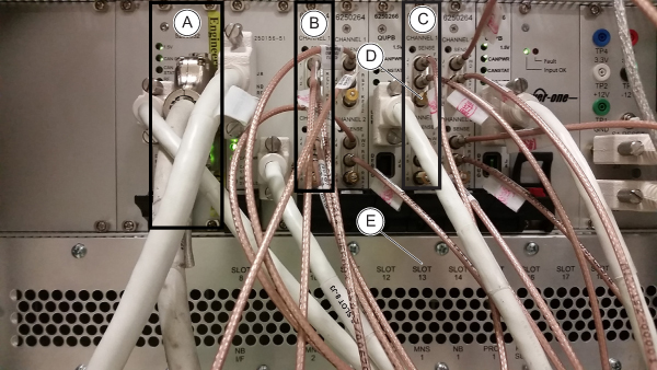
Figure 4. BB UPM RF detector and BB amplifier IF board
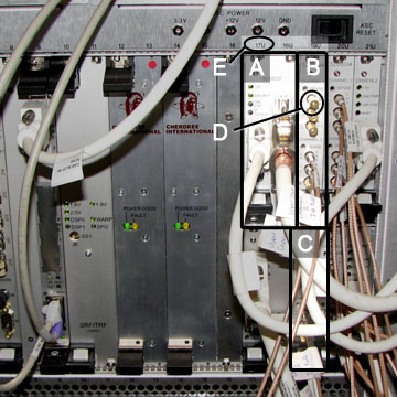
Item Description A BB amplifier IF board - slot 17U and 18U B BB UPM RF detector board 19U C BB UPM RF detector board 19L D 50 ohm terminators E Slot identification numbers -
(For Systems with ASC Chassis)
- At the front of the PGR cabinet, locate slots 10 and 13 on the UPM chassis. Remove the covers from the blank slots, remove the aluminum blanking insert panel if present, and insert one BB UPM RF detector board into each slot.
- Locate slot 6 in the UPM chassis. Remove the covers from the blank slots, remove the aluminum blanking insert panel if present, and insert the BB amp IF board.
- Locate the pre-installed white sub-D cable, PN 5722895, coiled and secured in the right side of the cabinet. Uncoil the cable and attach it to BB AIF board J3 in slot 6.
Figure 5. BB UPM RF detector and BB amplifier IF board
Item Description A BB amplifier IF board - slot 6 B BB UPM RF detector board 10 C BB UPM RF detector board 13 D 50 ohm terminators E Slot identification numbers
Installing MNS power connections
Procedure
-
(For systems with PDM) Remove the power distribution module (PDM) located in the top right corner of the PGR cabinet:
- Remove all cables connected to the front and top of the PDM.
Figure 6. Front of PDM
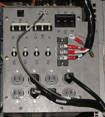
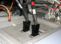
Figure 7. Top of PDM
- From the top of the PGR cabinet, remove the outer edge screws surrounding the PDM securing this unit to the rails. Remove all the screws from the PDM door.
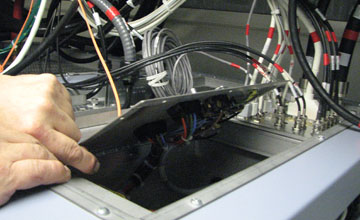
Figure 8. Open PDM door
- From the inside of the PDM, with the door open, unscrew the two cables locks (block retaining nuts) from the rear of the PDM, and disconnect the connections from the two terminal blocks. After the cables are disconnected, close the PDM door.note: It is important to note the orientation of the connections at the terminal blocks. Label the cables or record where to reconnect these cables later in the procedure.
Figure 9. PDM - disconnecting internal cable
- Slide the PDM out from the front of the PGR cabinet. Set it aside on a flat and safe surface.
- Remove all cables connected to the front and top of the PDM.
-
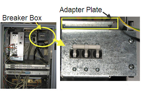
(For systems without PDM) Install the MNS breaker box in the top right corner of the PGR cabinet (for systems with PDM, proceed to Step 3):
- Remove the blank plate located in the top right corner of the PGR cabinet. Remove six screws from the top side of the cabinet.
- Attach the adapter plate to the MNS breaker box with one screw.
- Slide the adapter plate into position at the top of the PGR cabinet, secure it with screws (removed earlier from the top side of the cabinet), and attach the MNS breaker box to the right handrail in the PGR cabinet using two screws.
Figure 10. MNS breaker box positioning
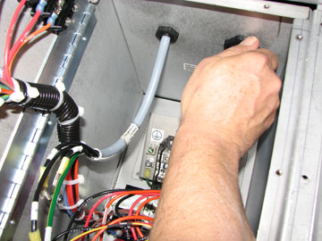
- Run the power cable from the MNS breaker box along the top edge of the PGR cabinet, and secure with cable ties as needed.
Figure 11. Cable route along top edge of PGR cabinet
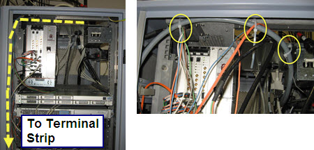
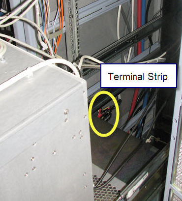
- Route the cable down the left side of the PGR cabinet to the terminal strip. (To access the terminal strip, the RF amplifier and CAM chassis (or ASC Chassis in case of ICE configuration) must be rolled out from the PGR cabinet.)
Figure 12. Terminal strip location
- Roll the RF amplifier out from the PGR cabinet. For details, refer to XRFD and Power Supply Replacement.
- (For systems with CAM chassis) Roll the CAM chassis out from the PGR cabinet. For details, refer to CAM Chassis Replacement.
- (For systems with ASC chassis) Roll the ASC chassis out of PGR Cabinet. For details, refer to KASC Assembly Replacement.
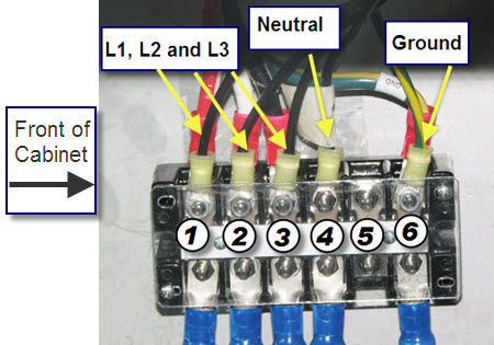
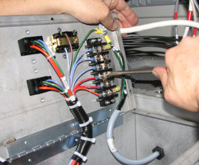
- note: It may be necessary to lean over the pulled out modules in the next step. Be careful not to put too much pressure on them.With a 5/16 inch socket wrench, connect the five wires from the power cable to the terminal strip as follows:
- Connect the ground wire to terminal 6.
- Connect wire labeled “N” (neutral) to terminal 4.
- Connect the L1, L2, and L3 wires to terminals 1, 2, and 3. (The specific order of these wires is not important.)
- Install the terminal strip plastic cover.
Figure 13. Terminal strip connections
- Ensure that the cables are securely fastened, and return the RF amplifier and the CAM or ASC chassis to their original positions.
- (For systems with or without PDM) At the PGR I/O panel, remove the blank plate from the J204 connection.
- Attach cable.
- (For Systems with CAM Chassis) Attach cable 5271096 to J204 on the underside of the I/O panel. Run this cable along the side of the PGR cabinet between the cabinet wall and the recon components. Attach the other end of the cable to the BB AIF board at CAM SLOT 17/18FU J5.
- (For Systems with ASC Chassis) Attach cable 5271096–2 to J204 on the underside of the I/O panel. Run this cable along the side of the PGR cabinet between the cabinet wall and the recon components. Attach the other end of the cable to the BB AIF board at ASC SLOT 6 J5.
Figure 14. I/O panel and cable locations
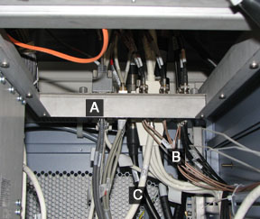
Item Description A PGR I/O panel B BNC cables C UPM cable - note:Attach BNC cables.
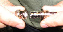
Before attaching the BNC cables (J200-203) to the I/O panel, connect the adapter (46-208990P1) to the BNC connector.
Figure 15. BNC connector and adapter
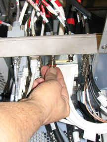
- (For systems with CAM Chassis) Attach the BNC cables to J200-203 connections on the underside of the I/O panel. Run these cables along the side of the PGR cabinet between the cabinet wall and the recon components. Attach the other ends to CAM slot 19FU J4, CAM slot 19FU J5, CAM slot 19FL J4, and CAM slot 19FL J5 .
- (For systems with ASC Chassis) Attach the BNC cables to J200-203 connections on the underside of the I/O panel. Run these cables along the side of the PGR cabinet between the cabinet wall and the recon components. Attach the other ends to ASC slot 10 J4, ASC slot 10 J5, ASC slot 13 J4, and ASC slot 13 J5 .
Figure 16. BNC connectors at I/O panel
- Add a 50 ohm terminator (2329754 or equivalent) to any unused port(s) on the RF detector boards.
- Tie wrap the MNS cables that run along the side of PGR cabinet.
Ensure the cables are not in the way of other components that may
require service.
Figure 17. Tie-wrapped MNS cables
-
(For sites with PDM) After all cables are connected properly and tie wrapped, slide the PDM into the PGR cabinet:
- From the top of the PGR cabinet, open the PDM door, and route the power cables through the opening at the rear of the PDM.
Figure 18. Cables from rear of PDM
- From the inside of the PDM, connect the cables and screw on the black retainer nuts to secure the cables.
Figure 19. Reconnecting cables in PDM
- Close the PDM door, attach the PDM to the rails with the surrounding screws, and screw the PDM door closed.
- Connect all cables to the top and front of the PDM as shown in Figure 6 and Figure 7.
- From the top of the PGR cabinet, open the PDM door, and route the power cables through the opening at the rear of the PDM.
Installing MNS in CAM or ICE chassis
Installing MNS hardware in PGR cabinet with XG2 and CAM
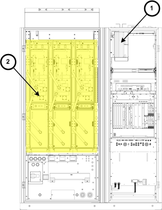
Figure 20. Cabinet with XG2 gradient hardware (no cronus chassis above ICN)
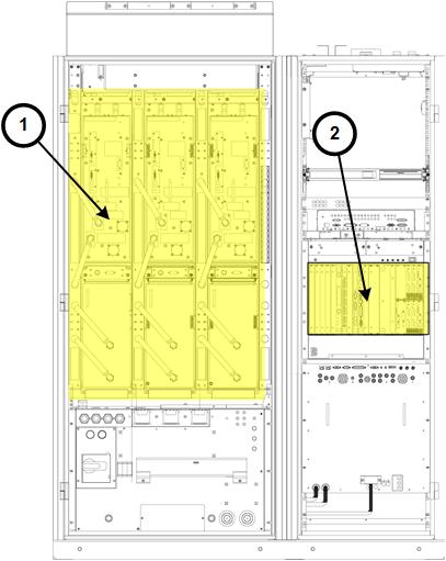
| Item | Description |
| 1 | XG2 gradient driver hardware |
| 2 | CAM |
Procedure
- Connect the fiber optic cable to J12 of the IXG board.
Figure 21. IXG board with cables for MNS configuration (MR750 and MR750w, DV VCP hardware)
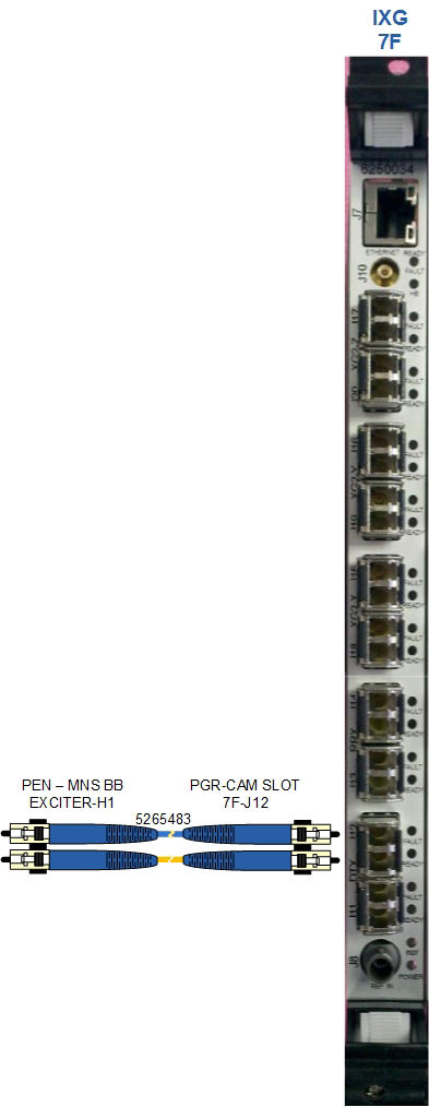
- This cable is the Gigalink (DVMR Link) from the exciter to the IXG.
Installing MNS hardware in PGR cabinet with XGD
Figure 22. Cabinet with previous hardware (pre-DV VCP)
| Item | Description |
| 1 | Cronus Chassis |
| 2 | XGD gradient driver hardware |
Procedure
- Locate slot 8F on the CAM chassis in the PGR cabinet. Remove
the cover from the blank slot.
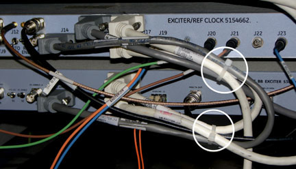
Figure 23. ERF and IXG boards with cables for MNS configuration (MR750w system)
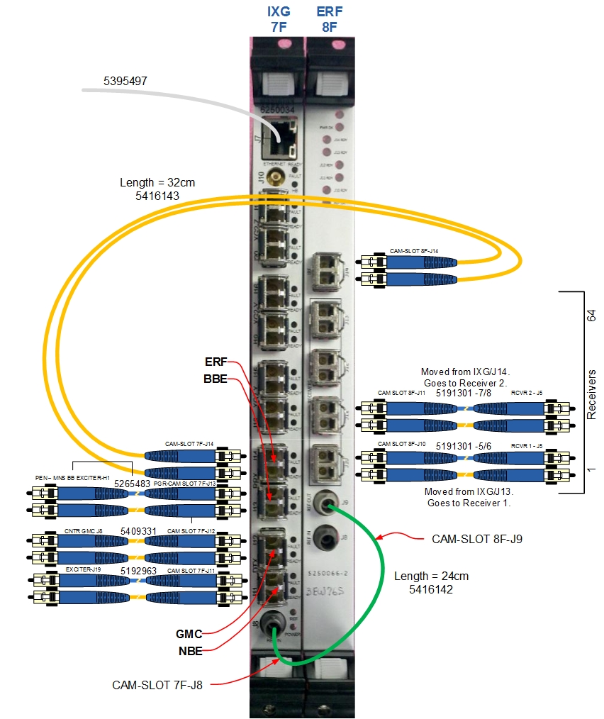
Click to download a higher-resolution PDF of the ERF and IXG boards in MNS configuration. PDF
- Insert the ERF board and seat it securely. Attach the ERF board to the CAM chassis using two screws: one at the top and another at the bottom.
- Remove the clock cable from J8 on the IXG board and connect it to J8 on the ERF board. The cable connects the ERF board (J8) to the exciter (J21).
- Daisy-chain the clock signal from the ERF board (J9) to the IXG board (J8) using the provided green cable (PN 5415142).
- Remove the channel 1 cable pair (PN 5191301-5/6) from J14 on the IXG board and connect it to J11 on the ERF board. This cable connects to receiver 2 (J5).
- Connect the ERF board (J14) to the IXG board (J14) using the cable pair (PN 5416143).
- Remove the cable from J13 on the IXG board and connect to J10 on the ERF board.
- Connect the cable (PN 5265483) from the new MNS exciter (H1) to J13 on the IXG board.
- Confirm that the cable pair (PN 5192963-3/4) connecting the IXG board (J11) to the exciter (J19) is connected.
Installing broadband exciter module (5300204-2) in CAM or ICE configuration
Procedure
- Connect the ends of cable 5262319 to J1 and cable 5265145 to J2 at the rear of the broadband exciter module before inserting it into the PEN cabinet.
- From the front of the cabinet, insert the module under the NB
exciter in the PEN cabinet. Route these cables to the rear of the
cabinet.
Figure 24. BB Exciter Module Location
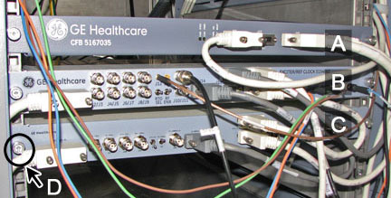
Item Description A CAN fiber-optic board (CFB) B NB exciter board C MNS BB exciter board D Thumbscrews securing module to cabinet frame - Attach the exciter board to the PEN cabinet with the two thumbscrews.
- In the scan room, loosen all the captive thumb screws, open the PEN access panel, and attach cable 5262319 to J31 and cable 5265145 to J33.
- Close the PEN access panel and tighten all thumb screws.
- Detach cable 5171626 from NB exciter J18, and reconnect it to broadband exciter J17_J1 lower. (This cable is not part of the MNS cable kit.)
- Locate the cables indicated in the table below, and connect
as directed.note: Route the PGR fiber cable (J12) along the left side of the PGR cabinet following the same route as the other bundled fiber cables.
Table 7 Broadband exciter cable connections Cable Part number Cable run number J number on MNS exciter Connected To Description 5266021 [None] J24 J14 of NB exciter Conveys clock and LO signal from NB to BB exciter 5165866-2 [None] J17_J1 (upper) J18 of NB exciter 1-wire data 5171626 [None] J17_J1 (lower) Pen cabinet IO (already installed) 1-wire data 5265483 E2024 H1 (Gigalink IO) (For CAM) J12 of IRF3 or IXG board
(For ICE) J32
CAM 5419641-2 [None] J15 J4 of SRPS DC power for MNS exciter 5271821 (if longer than required, “figure eight” the excess length and tie wrap) [None] J21 J16 of PEN cabinet top MNS Tx output of exciter 5262319 [None] J1 J31 of PEN cabinet wall MNS LO 5265145 E1309 J2 J33 of PEN cabinet wall MNS loopback - notice
- Tie wrap the cables together to ensure the cables are safely
contained within the cabinet, as follows:
- On the NB exciter, group cables from J14, J15, J17, J18, and J10.
- On the BB exciter, group cables from J14, J17, and J18.
Figure 25. PEN boards with cables tie-wrapped (pre-DV VCP example)
- Verify proper fiber optic cable connection from the exciter
to:
- J12 of the IRF3
- or J12 on IXG board
- or J32 on ICE
- Depending on system type.
|
Installing MNS upconverter – PN 5189655-2 (non-RoHS) or PN 5480090-2 (RoHS)
The MNS upconverter is installed on the rear pedestal of the magnet.
Figure 26. Upconverter location
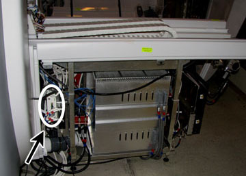
Procedure
- Install the MNS upconverter module into the upconverter bracket.
- Attach the mounting bracket with the MNS upconverter to the rear pedestal frame.
- Locate and connect the cables indicated in the table below.
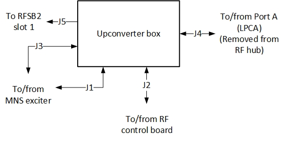
Table 8 MNS Upconverter Cable Connections Cable part number Cable run number J number on MNS upconverter Connected To Description 5166749-5, -8 M1308 J3 J31 of PEN cabinet wall via overhead cable track MNS LO 5169804-22, -31 M1309 J1 J33 of PEN cabinet wall via overhead cable track MNS loopback 5181541 M3356 J2 J11 - slot 11 board of RF hub Power and controls for MNS upconverter 5191729-5 [None] J4 LPCA connector A via LPCA cable track Connected to RF hub, slot 1, A1A2. Remove cable at RF hub and connect to J4 on the upconverter. 5191729-3 [None] J5 A1A2 - slot 1 board of RF hub 8W8 upconverter signal output. Install on slot previously removed on RF hub. note: On the RF control board, some cables may be need to be disconnected to properly connect the MNS upconverter cables. Reconnect these cables after the upconverter is fully installed.Figure 27. Upconverter box (Viewed from Patient End)
Installing LPCA cover
Procedure
- With the LPCA cover off, place the two LPCA rails on the top of the MNS LPCA cover so the notches are facing up. When viewing from the patient end, the right LPCA rail should have the notch farthest away, and the left rail should have the notch closest.
- Attach the rails to the cover by fastening the screws from the underside. (Screw heads are hidden underneath the cover.)
- Install the LPCA cover on the system and secure with four screws.
Ferrite installation
Procedure
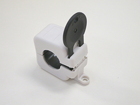
- warning
- Open the ferrites using the tool provided (Ferrites may be opened
and closed multiple times).
Figure 28. Ferrite and key
- Place one ferrite on each red and black gradient lead and squeeze
the ferrite to lock it closed.
Figure 29. Ferrites installed on gradient leads
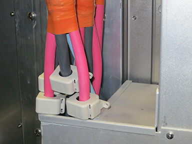
Installation notes:
- Ferrites fit loosely around the cables and do not require exact placement
- Ferrites may be placed behind the bottom cover of the pen-wall filter
- Ferrites do not require mechanical anchoring
- Do not place a ferrite around the smaller ground lead
 |
Installing MNS T/R switch on LPCA – PN 2354050 (non-RoHS) or PN 5409918 (RoHS)
Procedure
- Move the LPCA to a position for easy access, either to the front or rear of the magnet.
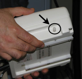
- Slide the MNS T/R switch on the two rails on the front of the
LPCA.note:The Delrin button at the side of the switch must be pushed to disengage the T/R switch from the LPCA rails.
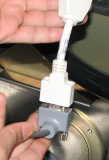
Figure 30. Delrin button on T/R switch
- Attach the cables of the MNS T/R switch to the MNS A-port adapter.
- Attach the A-port adapter to the A-port of the LPCA.
Installing MNS TX switch (PN 2254635)
Procedure
- Loosen the two thumbscrews to remove the support bracket from
the secondary PEN wall (SPW).
Figure 31. MNS TX switch setup on SPW
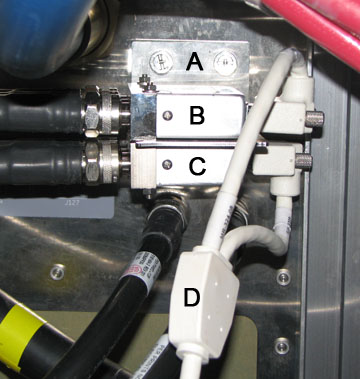
Item Description A Support bracket thumb screws B TX switch 1 C TX switch 2 (MNS) D Y-cable - Install the MNS TX switch to the support bracket, and connect
all cables as shown in the MNS cable map below. Refer to item C in Figure 31 for the location of the MNS TX switch.note: The cable connections for the 8 kW RF amplifier in following illustration are the same for both the AMT/Herley and CPC cabinets.note: The cable connections for the 8 kW RF amplifier in following illustration are the same for both the AMT/Herley and CPC cabinets.
Figure 32. MNS cable map for MR750/750w (PN 6250034 IXG board in CAM Slot 7F)
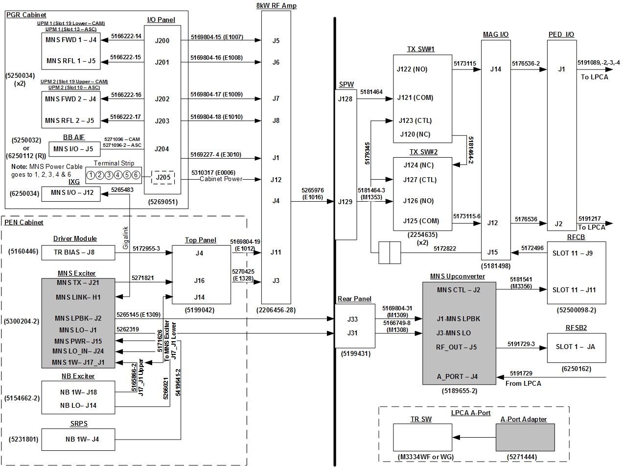 note: Click to download a higher-resolution PDF of the MNS cable map for MR750/750w (6250034 IXG board in CAM slot 7F): PDF
Figure 33. MNS cable map for MR750/MR750w with ICE & ASC chassis
 note: Click to download a higher-resolution PDF of the MNS Cable Map for MR750/MR750w with ICE & ASC Chassis: PDF.
 - Reattach the support bracket to the SPW.
- On the upper TX switch, remove the connection from J15 of the magnet I/O, and attach the Y-cable to J123 on the upper TX switch and to J127 on the MNS TX switch (lower). Connect the other end of the Y-cable
to the J15 magnet I/O connector.
Figure 34. Y-Cable connection to magnet I/O cable
Restoring system power
Procedure
- Notify all personnel working on the system that the system is being powered up.
- notice
- Remove LOTO from the RF amplifier and PEN cabinet. See the MR Service Safety Manual, PN 5452735.
- Remove LOTO from the PGR PDU/gradient subsystem. See the MR Service Safety Manual, PN 5452735.
- Open the plastic door over the front of the PDU breakers, and switch the appropriate subsystem breakers ON.
- Return any individual circuit breakers that were turned off to the ON position.
|
Installing spectroscopy software and configuring hardware
Procedure
- When the system begins to boot, do not bring up the applications.
Instead, log in as root and bring up Guided Install. note: It is possible that the customer changed the default password. If you cannot log in, contact the customer for the correct password.
- After the Guided Install window opens, select the Option Key tab.
- Install the MNS option key using eLicense. See Software Option Installation with eLicense Generated Keys.The option key delivered with the Hydrogen Only Spectroscopy Option (PROBE/SV) must also be installed.
- Place the rating plate on the rear of the GOC (if applicable).
- In Guided Install, open the Hardware Configuration screen.
Figure 35. Guided install hardware configuration screen
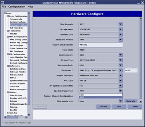
- For Spectro RF Amp Type, select AMT. (This is the correct selection regardless if the amplifier is AMT/Herley or CPC.)
- Ensure all other 3.0T settings are correct for the system.
- Modify if necessary, and save all changes.
- Reboot.
Verifying configuration settings
Procedure
- At the CSD, select the Utilities tab.
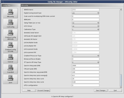
- Select the Config File Manager, and ensure
the following parameters match the definitions as stated:
- Spectroscopy RF Amplifier = yes to configure the MNS amplifier (amp to ready).
- Broadband Transceiver = yes to configure the MNS broadband transceiver (frequency change).
- Power Monitor Type = 4.
-
3T Spectro RF AMP Type = 0.
Figure 36. Config file manager screen
- Click Save Changes.
- Click Quit to exit the Config File Manager.
MNS exciter calibration
Procedure
- note: Each additional frequency calibration will add time to the TPS reset. Calibrate only the nuclei that the site needs; do not calibrate them all.In a C shell, go to the directory /w/config
- Type gedit mnsTgCal.cfgEnterThe mnsTgCal.cfg file contains a list of available nuclei.
- For the nuclei that the site needs calibrated, change the value from 0 to 1.
- Save the file.
- Type more mnsTgCal.cfgEnter and confirm that the changes were saved.At the next TPS reset or system restart, the nuclei will be calibrated.
Finalization
Procedure
- Do 8 kW 3.0T MNS Amplifier Calibration.
- Do UPM - MNS Setup and Calibration.
- Do UPM - MNS Functional Check.
- Do Doing a check scan.
- Do MNS 31P Functional Checks.
- Do any scan using head coil.
- Do a SaveInfo.