- id_13106450
- Version: 6.2
- Date: Mar 4, 2020 5:24:01 PM
8 kW 3.0T MNS amplifier calibration
Prerequisites
| Personnel requirements | |||
|---|---|---|---|
| Required persons | Preliminary requirements | Procedure | Finalization |
| 1 | - | 120 minutes | - |
| Tools and test equipment | |||
|---|---|---|---|
| Item | Quantity | Part number | Manufacturer |
| Flathead Screwdriver, at least 2 inches long | 1 | - | - |
| RF Power Measurement Kit (use one of the listed) | 1 | Kit PN 5307511-2 (Bird wattmeter) orKit PN 5307511-3 (Bird wattmeter) |
- |
| Digital Multimeter (DMM) | 1 | - | - |
| 3.0T 31P T/R Switch (available on site with customer) | 1 |
2354050 (non-RoHS) 5409918 (RoHS) |
- |
| Safety | ||
|---|---|---|
|
||
|
||
|


Follow this procedure after MNS Installation and Upgrade (3.0T) to calibrate either the CPC or AMT/Herley 8 kW amplifier for 3.0T.
The 8 kW AMT/Herley amplifier is the original amplifier and is easily identified by cables connecting to the rear of cabinet.
Figure 1. 8 kW AMT/Herley cabinet – front and back
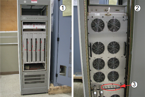
| Item | Description |
| 1 | Front of 8 kW AMT/Herley cabinet |
| 2 | Back of 8 kW AMT/Herley cabinet |
| 3 | Cable connections |
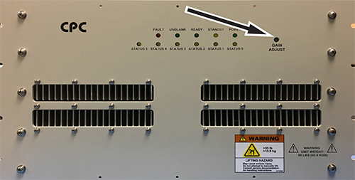
The CPC MNS amplifier is a new amplifier. Cables connect to the top of the cabinet for the CPC MNS amplifier. There are now two versions of the CPC MNS amplifier.
Figure 2. CPC cabinet – front and top
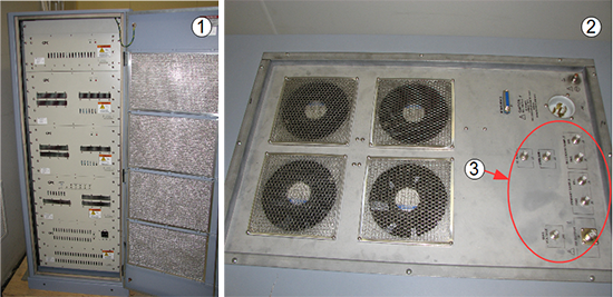
| Item | Description |
| 1 | Front of CPC cabinet |
| 2 | Top of CPC cabinet |
| 3 | Cable connections |
Calibration setup
System Setup
Procedure
- Make sure the system is idle and all coils have been removed from the magnet bore.
- Open the front door of the PEN cabinet.
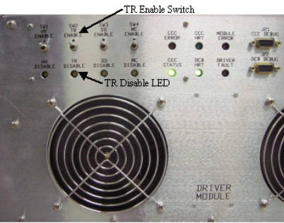
- On the front of the driver module, set the T/R switch to Disable. This disables the T/R
fault reporting.note: Leave HV and DD set to Enable.
Figure 3. Driver Module Switch
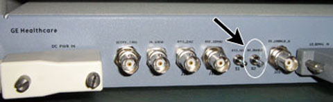
- Move the RF Enable S2 switch on the MNS
exciter to the DISABLE (down) position.
Figure 4. RF enable switch on exciter
- Proceed to set up the RF amplifier.
- (For CPC amplifier) There are no unique setup steps for the CPC amplifier. Proceed to Bird Wattmeter Setup.
Bird Wattmeter Setup
Procedure
- Move the RF Enable S2 switch on the MNS exciter to the DISABLE (down) position.
- Disconnect the MNS output cable.
- (For AMT/Herley amplifier) Disconnect J4 from the RF amplifier.
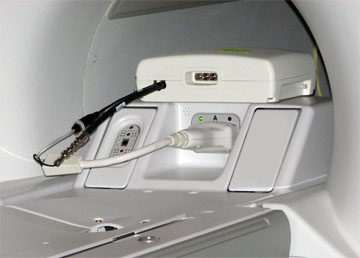
- (For the original CPC amplifier, part number 5411744) Open the rear door and disconnect J3 from the combiner module at the top of the cabinet.
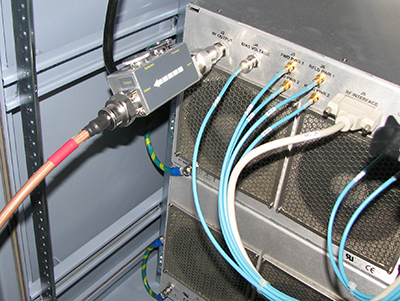
- (For the new CPC amplifier, part number 5750811) Open the rear door and disconnect J2 from the power amplifier at the bottom of the cabinet.
Figure 5. Coupler attached to J3 on combiner
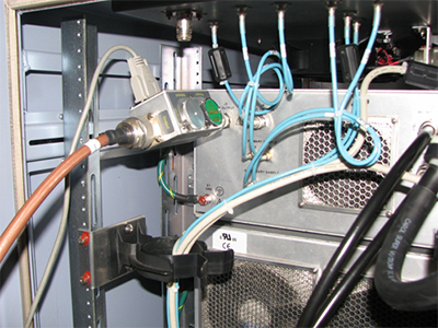
Figure 6. Coupler attached to J2 on power amplifier
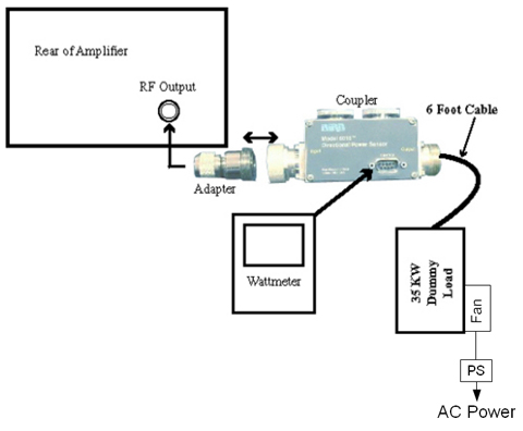
- Set up the wattmeter as shown below.
- (For AMT/Herley amplifier) Connect the input of the coupler to J4 (output connector).
- (For the original CPC amplifier, part number 5411744) Connect the input of the coupler to J3 (output connector). Do not connect the coupler at the top of the MNS cabinet as the cable may not reach the dummy load.
- (For the new CPC amplifier, part number 5750811) Connect the input of the coupler to J2 (output connector). Do not connect the coupler at the bottom of the MNS cabinet as the cable may not reach the dummy load.
Figure 7. Wattmeter setup – bird wattmeters
- Use a digital multimeter to measure the resistance between the dummy load RF connector center pin and the shield. Confirm a reading of 50Ω (± 5Ω). Replace the dummy load if the resistance is out of range.
- Make sure the dummy load fans are running before proceeding.
- Insert the 50 kW element (green 4300A374-2) into the forward sensor port, and make sure the arrow points from input to output.
- As a safety measure, place the 5 kW (blue 4300A374-6) or blank slug element into the reflected port, and make sure the arrow points from output to input (if applicable).
- Lock the elements into place using the locking tab on each sensor.
Figure 8. RF Coupler Setup
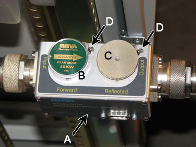
A
Wattmeter sensor
B
Forward sensor element
C
D
Sensor locking tabs
- Move the RF Enable S2 switch on the MNS exciter to the ENABLE (up) position.
- The power measurement kit can have one of two Bird wattmeters.
The setup instructions are different for each.
- (For Bird 5000-EX) Proceed to Setting up Bird 5000-EX wattmeter to measure forward MNS maximum power.
- (For Bird 5000-XT) Proceed to Setting up Bird 5000-XT Wattmeter to measure forward MNS maximum power.
Setting up Bird 5000-EX wattmeter to measure forward MNS maximum power
Figure 9. Bird 5000-EX wattmeter
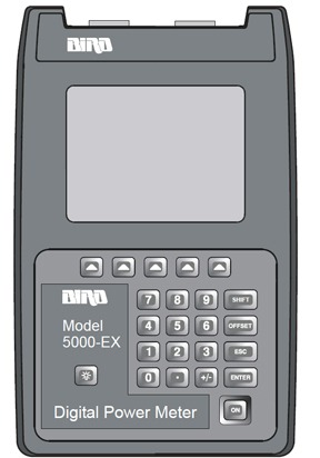
Procedure
- Press the ON button on the wattmeter. (If the coupler and sensor are not correctly attached to the amplifier you will see a “No Sensor” indication.)
- Select the arrow ▲ button under Scale.
- Enter 50000 to set the range.
- Select the ENTER button.
- Check the setting by selecting the arrow button under Scale.
- Press the ENTER button to exit.
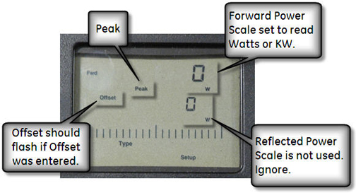
- Select the arrow button under Fwd Units. Make sure the scale reads W (or kW on some wattmeters). If the scale reads dBm, select the arrow button under Fwd Units again to toggle the scale to read W (Watts) or kW (kiloWatts) on the TOP, forward power scale. Ignore the BOTTOM, reflected power scale value. It is not used during maximum power calibration.
- Select the SHIFT button.
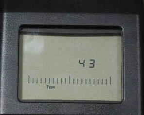
- Select the arrow button under Setup.
This displays the sensor type configured in the wattmeter. This procedure uses sensor type 43, which is optimized for peak power measurement.
- Verify that the output reads 43, and
then press the ENTER button.
Figure 10. Wattmeter display set to read
- Press the ENTER button.
- Press the arrow ▲ button under Type and then toggle to change the unit of measurement to Peak.
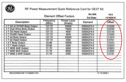
- All kits require an offset to make sure of accurate measurement. Locate the Element Offset Factors card in the kit.
Find the offset for “1.5 T Body Output.”
Figure 11. Example element offset factors card
- Press the Offset button on the wattmeter.
Enter the numerical value from the offset card and press the Enter button.note: To enter a negative value, first enter the numerical value, then the minus symbol (–).
Figure 12. Wattmeter set to display peak power
- Proceed to Calibrate MNS amplifier.
Setting up Bird 5000-XT Wattmeter to measure forward MNS maximum power
Figure 13. Bird 5000-XT wattmeter
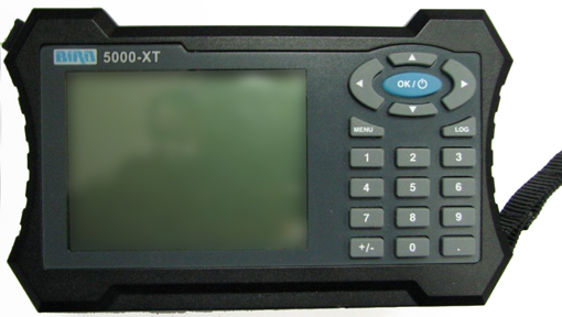
Procedure
- Press the OK button on the wattmeter.
- Press the MENU button. Press the ▼ button to SCALE MENU, and then press OK.
- Press 50000 to set the range, and then press OK.
- Check the setting by pressing ▼ to SCALE MENU, and then press OK.
- Press OK to exit. Press ◄ to return to measurement mode.
- Press ▲ to make sure the scale reads W (or uW or kW on some wattmeters). If the scale reads dBm, press ▲ again to toggle the scale to read W (or uW or kW on the TOP, forward power scale. Ignore the BOTTOM, reflected power scale value. It is not used during maximum power calibration.
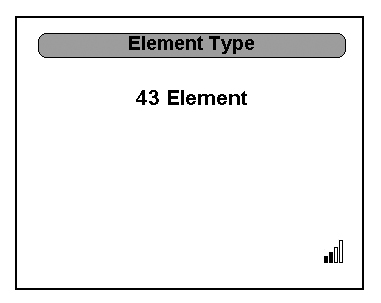
- Press MENU.
- Press ▼ to select ELEMENT TYPE, and then
press OK.
This displays the sensor type configured in the wattmeter. This procedure uses sensor type 43, which is optimized for peak power measurement.
- Verify that the output reads 43, and then
press OK.
Figure 14. Wattmeter set to read
- Press OK. Press ◄ to return to measurement mode.
- All kits require an offset to make sure of accurate measurement. Locate the Element Offset Factors card in the kit.
Find the offset for “1.5T Body Output.”
Figure 15. Example element offset factors card
- Press the MENU button on the wattmeter.
Select OFFSET, and then press OK. Enter in the numerical value that was displayed on the kit’s
offset card and press OK. (The wattmeter rounds
to three significant digits.) Press ◄ to return to measurement mode.note: To enter a negative value, first enter the numerical value, and then the minus symbol (–).
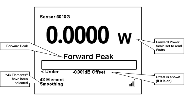
- Press MENU. Press ▼ until SMOOTHING is selected, and then press OK.
- To verify that SMOOTHING has been set, press ▼ until SMOOTHING is selected, and then press OK.
- The wattmeter should display 4 Samples. Press OK.
- Press ◄ to return to measurement mode.
Figure 16. Wattmeter set to display peak power
- Proceed to Calibrate MNS amplifier
Calibrate MNS amplifier
Procedure
- Connect the MNS 31P T/R switch to the LPCA.
Figure 17. MNS 31P TR switch connection to LPCA
- Landmark in the center of the head coil area and select Advance to Scan.
For AMT/Herley amplifier
Procedure
- Slowly increase TG to 200 or until the wattmeter reads 8 kW. Specification is 7.2 kW to 8.2 kW.note: Make attenuator adjustments slowly. Give the wattmeter about 5 seconds between changes to settle. If the amplifier faults, reverse the previous adjustments and restart the calibration procedure through the UPM Tool.
- If TG equals 200, but the wattmeter reads less than 7.2 kW, rotate 0.5 dB adjustment control counterclockwise to achieve a specification is 7.2 kW to 8.2 kW.
- If output is still less than 7.2 kW and TG = 200:
- Adjust the 0.5 dB adjustment control for minimum wattmeter reading.
- Reduce TG from 200 to 50, and then rotate the 6.0 dB adjustment control counterclockwise by one step.
- Slowly increase TG from 50 to 200, and then adjust the 0.5 dB control for the correct reading on the wattmeter.
- If the wattmeter reads between 7.2 kW and 8.2 kW:
- Reduce TG to 0 and then rotate the 6.0 dB adjustment control clockwise by one step.
- Return to Step 1.
- Select Done to end manual prescan.
- After the amplifier is calibrated to 7.2 kW to 8.2 kW at TG = 200, select Done to end manual prescan. Switch to the UPM Tool and select Success on the RF Amp Calibration popup.
- Proceed to Finalization.
For CPC amplifier
Procedure
- Slowly increase TG to 200 or until the
wattmeter reads 8 kW. Specification is 7.2 kW to 8.2 kW.note: Make attenuator adjustments slowly. Give the wattmeter about 5 seconds between changes to settle. If the amplifier faults, reverse the previous adjustments and restart the calibration procedure through the UPM Tool.
- Verify that RF output is 7.2 kW to 8.2 kW at TG of 200.
- Adjust for proper RF output by either toggling the switches
on the original amplifier, or by adjusting the potentiometer on the
new amplifier.
Figure 18. Control switches on CPC amplifier
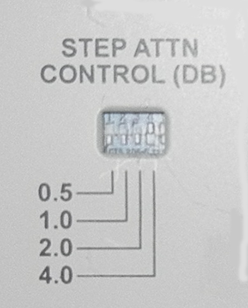
Figure 19. Potentiometer on CPC amplifier
- After the amplifier is calibrated to 7.2 kW to 8.2kW at TG = 200, select Done to end manual prescan. Switch to the UPM Tool and select Success on the RF Amp Calibration popup.
- Proceed to Finalization.