- id_13107536
- Version: 3.0
- Date: Aug 29, 2019 1:39:21 AM
XRFD and power supply replacement
Prerequisites
| Required persons | Preliminary requirements | Procedure | Finalization |
|---|---|---|---|
| 1 | 5 minutes | 90-120 minutes | 5 minutes |
| Item | Quantity | Effectivity | Part number | Manufacturer |
|---|---|---|---|---|
| Hoist Service Kit | 1 | - |
5196226 |
- |
| Non-Magnetic Tool Kit (or equivalent) | 1 | - |
5113258 |
- |
| Item | Quantity | Effectivity | Part number | Manufacturer |
|---|---|---|---|---|
| Towels | N/A | - | - | - |
| Tie wraps | 3-5 | - | - | - |
| Item | Quantity | Effectivity | Part number | Manufacturer |
|---|---|---|---|---|
| XRFD | 1 | - |
5135844-3 |
- |
| XRFD Power Supply | 1 | - |
5135844-4 |
- |
|


| Condition | Reference | Effectivity |
|---|---|---|
| The PGR PDU/gradient subsystem must be locked and tagged out before starting this procedure. See the MR Service Safety Manual, PN 5452735. | - | - |
| Before disconnecting any coolant lines on the front of the XRFD unit, shut down the PPMP at the HEC. | - | - |
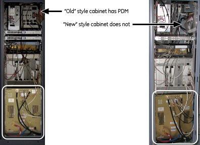
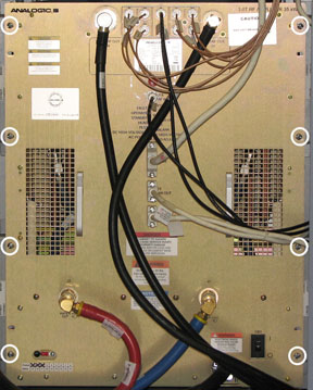
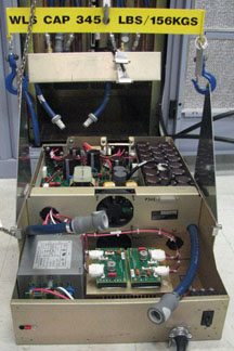
This document contains four procedures (two for each style of cabinet): XRFD replacement and XRFD power supply replacement. Both units are in the PGR cabinet. The XRFD weighs about 315 pounds and the XRFD PS weighs 80 pounds. Each unit weighs enough that a hoist kit is required. This document details the correct way to use a hoist kit to safely remove and replace the XRFD and XRFD PS units.
Figure 1. PGR cabinet: XRFD and power supply
Choose appropriate instruction
XRFD replacement (with PDM)
Procedure
- Power down the host PC.
- Perform LOTO on the PGR cabinet. See the MR Service Safety Manual, PN 5452735.
- Before disconnecting any coolant lines on the front of the XRFD unit, shut down the PPMP at the HEC by pressing ▲ and F3 simultaneously. Then, switch the PPMP circuit breaker to OFF.
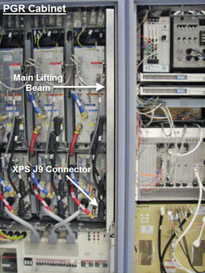
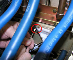
- Before setting up the hoist kit, detach the XPS J9 connector
to properly remove the main lifting beam.
Figure 2. Lifting beam and connector in PGR cabinet
- See Hoist Service Kit and Lifting Accessories to set up and secure the hoist.
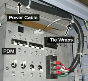
- Remove the tie wraps that hold the power cable. The cable goes
underneath the XRFD and along the side of the cabinet to the top of
the PDM.
Figure 3. Tie Wraps on Power Cable
 note: Before continuing, be prepared to absorb any leakage from the coolant lines with a towel in hand as the line is disconnected.
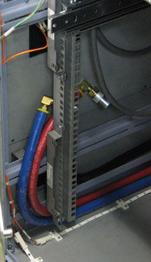
 - Disconnect the power cable at the terminal, the cables on the
front of the XRFD, and the coolant lines. Carefully move the cables
and lines to the side of the cabinet, so the surrounding area is free
from any obstructions when the amplifier is pulled out.
Figure 4. Coolant lines placement
- Unscrew the eight attachment screws.
Figure 5. XRFD attachment screws
- Using the two front handles, carefully slide out the XRFD unit.
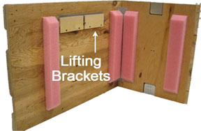
- Attach the lifting brackets (found in the XRFD FRU crate) to
both sides of the XRFD. The attachment screws are captive screws and
remain with the lifting brackets.
Figure 6. Inside FRU Crate - Lifting Brackets
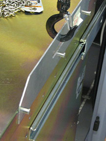
- Hook the winch and spreader bar from the hoist kit to the lifting
bracket. Ratchet the winch to tighten the chain.note: Make sure the hook is seated in the lifting bracket. If not, the weight can shift causing harm to the equipment or the engineer.
Figure 7. Lifting brackets with seated hook
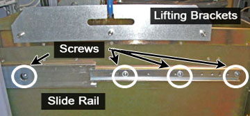
- With the XRFD unit supported by the hoist kit, unscrew the four
screws and remove the slide rails from both sides.
Figure 8. XRFD Slide Rails
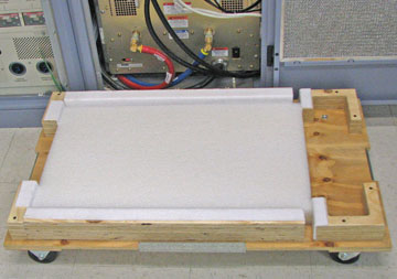
- The FRU is packaged in a wooden crate. For the XRFD, there are
four parts to the FRU crate. Remove the top of the wooden crate and
turn it on its base. The XRFD being removed can be placed into the
top. Roll the top underneath the XRFD and lock the wheels so that
the container does not move.
Figure 9. Base of FRU crate
- Ratchet the winch to lower the XRFD into the package.
- Remove the hook from the lifting bracket.
- Unscrew the lifting brackets from the sides of the XRFD. Roll the removed XRFD to the side.
- Remove the center sections of the FRU crate.
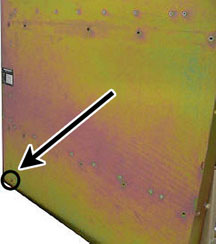
- Remove the shipping screw from each side of the XRFD FRU.
Figure 10. Shipping Screw on XRFD FRU
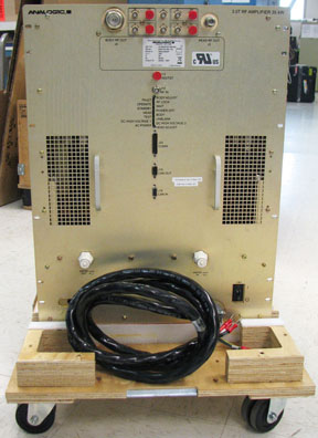
- Bring the FRU to the front of the cabinet. Attach the slide
rails to the FRU.
Figure 11. XRFD FRU
- Attach the lifting brackets to the sides of the new amplifier.
- Attach the new XRFD lifting brackets to the winch and spreader
bars.note: Make sure the hook is seated in the lifting bracket. If not, the weight can shift causing harm to the equipment or the engineer.
- Ratchet the winch to tighten the chains and begin lifting the unit. Slide out the rail a short amount to see how high to lift the new XRFD. The XRFD slide rails and the cabinet slide rails must align for correct insertion.
- When the slide rails are aligned, pull the slide rails out a short distance to get each side started. After both slide rails are attached, pull the slide rails onto the FRU until you hear a click, indicating that the unit is docked in the rails. Ensure the XRFD is secure on the rails
- Unhook the winch and spreader bars from the lifting brackets.
Remove the lifting brackets from the sides of the new XRFD.
Place the lifting brackets in the XRFD FRU crate.
- Slide the XRFD into the cabinet completely.
- Attach the XRFD to the cabinet using the front eight attachment screws Figure 5.
- Reconnect the cables and coolant lines to the XRFD.
- note: Before continuing, be prepared to absorb any leakage from the coolant lines with a towel in hand as the line is connected.Disassemble the hoist kit (see Hoist Service Kit and Lifting Accessories).
- Return the main lifting beam to the PGR cabinet. After the beam is secure, reconnect the XPS J9 connector. Return the support tube to the HEC.
- Proceed to Step 1.
XRFD Power supply replacement (with PDM)
Procedure
- Power down the host PC.
- Apply LOTO on the PGR cabinet. See the MR Service Safety Manual, PN 5452735.
- Before disconnecting any coolant lines on the front of the XRFD unit, shut down the PPMP at the HEC. Press ▲ F3 simultaneously to stop the pump. Then, switch the PPMP circuit breaker to OFF.
- Before setting up the hoist kit, detach the XPS J9 connector to properly remove the main lifting beam Figure 2.
- See Hoist Service Kit and Lifting Accessories to set up and secure the hoist.
- Remove the tie wraps that hold the power cable. The cable goes under the XRFD and along the side of the cabinet to the top Figure 3.
- note: Before continuing, be prepared to absorb any leakage from the coolant lines with a towel in hand as the line is disconnected.Disconnect the power cable at the terminal, the cables on the front of the XRFD PS, and the coolant lines. Carefully move the cables and lines to the side of the cabinet, so the surrounding area is free when the PS unit is pulled out Figure 4.
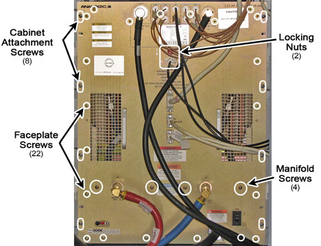
- Unscrew the eight large screws that attach the XRFD to the cabinet,
the four screws that attach to the manifold, the twenty-two faceplate
screws, and the two BNC locking nuts.
Figure 12. XRFD - all Sscrews
- Remove the XRFD PS faceplate. After the faceplate is pulled away from the unit, do the following steps:
- Loosen the two front thumbscrews to allow the manifold tray to swing up.
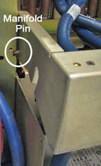
- Lift the manifold tray and pull it out of the way of the power supply. The manifold has a spring loaded pin that allows the tray to swivel up and down.
Figure 13. Manifold Pin on XRFD PS
- Disconnect the two internal coolant lines.
- Locate the long thin retaining bracket mounted directly above the supply opening. Remove the screws and then the bracket.
- note: If the supply does not slide forward, extend the XRFD from the cabinet and check that the shipping screws have been removed from each side of the XRFD.Remove the two sub-D cables, PSU-1 and PSU-2.
Figure 14. Sub-D cables
- Slide out the XRFD PS unit.
- Attach the lifting brackets to both sides of the XRFD PS. The lifting brackets can be found in the XRFD PS FRU crate Figure 6. The attachment screws are captive screws and remain with the lifting brackets.
- Hook the winch and spreader bar from the hoist kit to the lifting
bracket. Ratchet the winch to tighten the chain.note: Make sure the hook is seated in the lifting bracket. If not, the weight can shift causing harm to the equipment or the engineer.
Figure 15. XRFD PS with hoist kit
- The FRU is packaged in a wooden crate. For the XRFD PS, there are three parts to the FRU crate. Remove the top of the wooden crate and turn it on its base. The XRFD PS being removed can be placed into the top. Roll the top underneath the XRFD PS and lock the wheels so that the container does not move.
- Ratchet the winch to lower the XRFD PS into the package.
- Remove the hook from the lifting bracket.
- Unscrew the lifting brackets from the sides of the XRFD. Roll the removed XRFD PS to the side.
- Remove the center section of the FRU crate.
- Remove the shipping cover from the XRFD PS FRU.
- Attach the shipping cover to the top of the removed XRFD PS FRU.
- Bring the FRU to the front of the cabinet and attach the lifting brackets to the sides of the new PS.
- Attach the new XRFD PS lifting brackets to the winch and spreader
bars.note: Make sure the hook is seated in the lifting bracket. If not, the weight can shift causing harm to the equipment or the engineer.
- Ratchet the winch to tighten the chains and begin lifting the unit.
- Place the XRFD PS into the XRFD.
- Unhook the winch and spreader bars from the lifting brackets.
Remove the lifting brackets from the sides of the new XRFD PS.note: Place the lifting brackets into the XRFD PS FRU crate.
- Slide the XRFD PS into the XRFD. After the XRFD PS is completely in the XRFD, do the following steps:
- Attach the two sub-D cables.
- Attach the upper retaining bracket.
- Connect the two quick disconnect lines.
- Release the manifold and swing the tray down.
- Tighten the two front thumbscrews.
- Attach the XRFD faceplate.
- note: Before continuing, be prepared to absorb any leakage from the coolant lines with a towel in hand as the line is connected.Reconnect the cables and coolant lines to the XRFD. For the power cable, use the tie wraps along the inner edge of the cabinet and along the top so that the cable is safely out of the way.
- Attach the XRFD to the cabinet using the front eight attachment screws.
- Disassemble the hoist kit (see Hoist Service Kit and Lifting Accessories).
- Return the main lifting beam to the PGR cabinet. After the beam is secure, reconnect the XPS J9 connector. Return the support tube to the HEC.
- Proceed to Step 1.
XRFD replacement (without PDM)
Procedure
- Power down the host PC.
- Apply LOTO on the PGR cabinet. See the MR Service Safety Manual, PN 5452735.
- Before disconnecting any coolant lines on the front of the XRFD unit, shut down the PPMP at the HEC by pressing ▲ and F3 simultaneously. Then switch the PPMP circuit breaker to OFF
- Before setting up the hoist kit, detach the XPS J9 connector
to properly remove the main lifting beam.
Figure 16. Lifting beam and connector in PGR cabinet
- See Hoist Service Kit and Lifting Accessories to set up and secure the hoist.
- note: Before continuing, be prepared to absorb any leakage from the coolant lines with a towel in hand as the line is disconnected.Disconnect the cables on the front of the XRFD, and disconnect the coolant lines. Carefully move the cables and lines to the side of the cabinet, so the surrounding area is free from any obstruction when the amplifier is pulled out.
Figure 17. Coolant lines placement
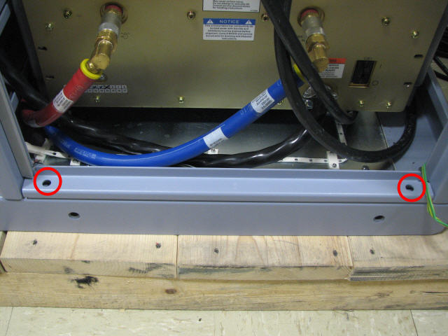
- Remove the PGR base plate by unscrewing the two attached screws.
Figure 18. PGR Base Plate
- Unscrew the eight attachment screws.
Figure 19. XRFD attachment screws
- Using the two front handles, carefully slide out the XRFD unit.
- Attach the lifting brackets (found in the FRU crate) to both
sides of the XRFD. The attachment screws are captive screws and remain
with the lifting brackets.
Figure 20. Inside FRU crate - lifting brackets
- Hook the winch and spreader bar from the hoist kit to the lifting
bracket. Ratchet the winch to tighten the chain.note: Make sure the hook is seated in the lifting bracket. If not, the weight can shift causing harm to the equipment or engineer.
Figure 21. Lifting brackets with seated hook
- With the XRFD unit supported by the hoist kit, unscrew the four
screws and remove the slide rails from both sides.
Figure 22. XRFD slide rails
- The FRU is packaged in a wooden crate. For the XRFD, there are
four parts to the FRU crate. Remove the top of the wooden crate and
turn it on its base. The XRFD being removed can be placed into the
top. Roll the top under the XRFD and lock the wheels so that the container
does not move.
Figure 23. Base of FRU Crate
- Ratchet the winch to lower the XRFD into the package.
- Remove the hook from the lifting bracket.
- Roll the XRFD to the side to allow access to the cabinet base.
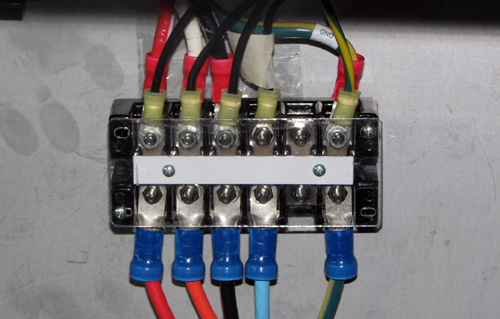
- Disconnect the XRFD power cable from the terminal.
Figure 24. XRFD terminal block
- Unscrew the lifting brackets from the sides of the XRFD. Roll the removed XRFD to the side.
- Remove the center sections of the FRU crate.
- Remove the shipping screw from each side of the XRFD FRU.
Figure 25. Shipping screw on XRFD FRU
- Bring the FRU to the front of the cabinet. Attach the power
cable to the terminal and attach the slide rails to the FRU.
Figure 26. XRFD FRU
- Attach the lifting brackets to the sides of the new XRFD.
- Attach the new XRFD lifting brackets to the winch and spreader
bars.note: Make sure the hook is seated in the lifting bracket. If not, the weight can shift causing harm to the equipment or the engineer.
- Ratchet the winch to tighten the chains and begin lifting the unit. Slide out the rail a short amount to see how high to lift the XRFD. The XRFD slide rails and the cabinet slide rails must align for correct insertion.
- When the slide rails are aligned, pull the slide rails out a short distance to get each side started. After both slide rails are attached, pull the slide rails onto the FRU until you hear a click, indicating that the unit is docked in the rails. Ensure the XRFD is secure on the rails.
- Unhook the winch and spreader bars from the lifting brackets.
Remove the lifting brackets from the sides of the new XRFD.
Place the lifting brackets into the XRFD FRU crate.
- Slide the XRFD into the cabinet completely.
- Attach the XRFD to the cabinet using the front eight attachment screws (see Figure 19).
- Reattach the PGR base plate using the two attachment screws (see Figure 18).
- note: Before continuing, be prepared to absorb any leakage from the coolant lines with a towel in hand as the line is connected.Reconnect the remaining cables and coolant lines to the XRFD.
- Disassemble the hoist kit (see Hoist Service Kit and Lifting Accessories).
- Return the main lifting beam to the PGR cabinet. After the beam is secure, reconnect the XPS J9 connector. Return the support tube to the HEC.
- Proceed to Step 1.
XRFD power supply replacement (without PDM)
Procedure
- Power down the host PC.
- Perform LOTO on the PGR cabinet. See the MR Service Safety Manual, PN 5452735.
- Before disconnecting any coolant lines on the front of the XRFD unit, shut down the PPMP at the HEC. Press ▲ and F3 simultaneously to stop the pump. Then switch the PPMP circuit breaker to OFF.
- Before setting up the hoist kit, remove the XPS J9 connector to properly remove the main lifting beam (see Figure 16).
- See Hoist Service Kit and Lifting Accessories to set up and secure the hoist.
- note: Before continuing, be prepared to absorb any leakage from the coolant lines with a towel in hand as the line is disconnected.Disconnect the cables on the front of the XRFD PS, and disconnect the coolant lines. Carefully move the cables and lines to the side of the cabinet, so the surrounding area is free when the PS unit is pulled out (see Figure 17).
- Unscrew the eight attachment screws.
Figure 27. XRFD attachment screws
- Using the two front handles, carefully slide out the XRFD unit.
- Attach the lifting brackets (found in the FRU crate) to both
sides of the XRFD. The attachment screws are captive and remain with
the lifting brackets.
Figure 28. Inside FRU crate - lifting brackets
- Hook the winch and spreader bar from the hoist kit to the lifting
bracket. Ratchet the winch to tighten the chain. note: Make sure the hook is seated in the lifting bracket. If not, the weight can shift, causing harm to the equipment or engineer.
Figure 29. Lifting brackets with seated hook
- With the XRFD unit supported by the hoist kit, remove the XRFD from the slide rails.
- Ratchet the winch to lower the XRFD onto the floor, making sure to allow space to disconnect the power cable.
- Disconnect the XRFD power cable from the terminal and bring
to the front of the XRFD.
Figure 30. XRFD terminal block
- Ratchet the winch to tighten the chains and begin lifting the unit. Slide out the rail a short amount to see how high to lift the XRFD. The XRFD slide rails and the cabinet slide rails must align for correct insertion.
- When the slide rails are aligned, pull the slide rails out a short distance to get each side started. After both slide rails are attached, pull the slide rails onto the FRU until you hear a click, indicating that the unit is docked in the rails. Ensure the XRFD is secure on the rails.
- Unhook the winch and spreader bars from the lifting brackets. Remove the lifting brackets from the sides of the XRFD.
- Slide the XRFD completely into the cabinet.
- Unscrew the four screws that attach to the manifold, the twenty-two
faceplate screws, and the two BNC locking nuts.
Figure 31. XRFD - all screws
- Remove the XRFD PS faceplate. After the faceplate is pulled away from the unit, do the following steps:
- Loosen the two front thumbscrews to allow the manifold tray to swing up.
- Lift the manifold tray and pull it out of the way of the power supply. The manifold has a spring loaded pin that allows the tray to swivel up and down.
Figure 32. Manifold Pin on XRFD PS
- Disconnect the two internal coolant lines.
- Locate the long thin retaining bracket mounted directly above the supply opening. Remove the screws and then remove the bracket.
- note:Remove the two sub-D cables, PSU-1 and PSU-2.
If the supply does not slide forward, extend the XRFD from the cabinet and check that the shipping screws have been removed from each side of the XRFD.
Figure 33. Sub-D cables
- Slide out the XRFD PS unit.
- Attach the lifting brackets to both sides of the XRFD PS. The attachment screws are captive screws and remain with the lifting brackets.
- Hook the winch and spreader bar from the hoist kit to the lifting
bracket. Ratchet the winch to tighten the chain.note: Make sure the hook is seated in the lifting bracket. If not, the weight can shift causing harm to the equipment or the engineer.
Figure 34. XRFD PS with hoist kit
- The FRU is packaged in a wooden crate. For the XRFD PS, there are three parts to the FRU crate. Remove the top of the wooden crate and turn it on its base. The XRFD PS being removed can be placed into the top. Roll the top under the XRFD PS and lock the wheels so that the container does not move.
- Ratchet the winch to lower the XRFD PS into the package.
- Remove the hook from the lifting bracket.
- Unscrew the lifting brackets from the sides of the XRFD. Roll the removed XRFD PS to the side.
- Remove the center section of the FRU crate.
- Remove the shipping cover from the XRFD PS FRU.
- Attach the shipping cover to the top of the removed XRFD PS FRU.
- Bring the FRU to the front of the cabinet and attach the lifting brackets to the sides of the new power supply.
- Attach the new XRFD PS lifting brackets to the winch and spreader
bars.note: Make sure the hook is seated in the lifting bracket. If not, the weight can shift causing harm to the equipment or the engineer.
- Ratchet the winch to tighten the chains and begin lifting the unit.
- Place the XRFD PS into the XRFD.
- Unhook the winch and spreader bars from the lifting brackets. Remove the lifting brackets from the sides of the new XRFD PS.
- Slide the XRFD PS into the XRFD. After the XRFD PS is completely
in the XRFD, perform the follow steps:
- Attach the two sub-D cables.
- Attach the upper retaining bracket.
- Connect the two quick disconnect lines.
- Release the manifold and swing the tray down.
- Tighten the two front thumbscrews.
- Attach the XRFD faceplate.
- Using the two front handles, carefully slide out the XRFD unit.
- Attach the lifting brackets to both sides of the XRFD. The attachment screws are captive and remain with the lifting brackets.
- Hook the winch and spreader bar from the hoist kit to the lifting
bracket. Ratchet the winch to tighten the chain.note: Make sure the hook is seated in the lifting bracket. If not, the weight can shift, causing harm to the equipment or the engineer.
Figure 35. Seated hook
- With the XRFD unit supported by the hoist kit, remove the XRFD from the slide rails.
- Ratchet the winch to lower the XRFD onto the floor, making sure to allow space to attach the power cable.
- Attach the XRFD power cable to the terminal block.
Figure 36. XRFD terminal block
- Ratchet the winch to tighten the chains and begin lifting the unit. Slide out the rail a short amount to see how high to lift the new XRFD. The XRFD slide rails and the cabinet slide rails must align for correct insertion.
- When the slide rails are aligned, pull the slide rails out a short distance to get each side started. After both slide rails are attached, pull the slide rails on to the FRU until you hear a click, indicating that the unit is docked in the rails. Ensure the XRFD is secure on the rails.
- Unhook the winch and spreader bars from the lifting brackets.
Remove the lifting brackets from the sides of the new XRFD.note: Place the lifting brackets into the XRFD FRU crate.
- Slide the XRFD completely into the cabinet.
- Attach the XRFD to the cabinet using the front eight attachment screws.
- note: Before continuing, be prepared to absorb any leakage from the coolant lines with a towel in hand as the line is connected.Reconnect the cables and coolant lines to the XRFD.
- Attach the XRFD to the cabinet using the front eight attachment screws.
- Disassemble the hoist kit (see Hoist Service Kit and Lifting Accessories).
- Return the main lifting beam to the PGR cabinet. After the beam is secure, reconnect the XPS J9 connector. Return the support tube to the HEC.
- Proceed to Step 1.
Finalization
Procedure
- Remove LOTO from the PGR cabinet. See the MR Service Safety Manual, PN 5452735.
- Power up the host PC.
- Turn on the PPMP circuit breaker at the HEC. Start the pump by pressing ▲ and F3 simultaneously.
- If the complete XRFD was replaced, Calibrating RF Amplifier and UPM.note: XRFD calibration is not necessary if only the XRFD PS was replaced.
- Remove coolant from the old XRFD unit using the manual coolant removal tool Coolant Draining.
- After attaching the center sections of the FRU package to the
removed FRU unit base, attach the top of the FRU crate to prepare
the FRU for return.note: The XRFD has two center sections. The XRFD PS only has one center section.