- id_13106454
- Version: 4.4
- Date: Mar 4, 2020 12:56:35 PM
UPM - MNS functional check
Prerequisites
| Personnel requirements | |||
|---|---|---|---|
| Required persons | Preliminary requirements | Procedure | Finalization |
| 1 | - | 15 minutes | 5 minutes |
| Tools and test equipment | |||
|---|---|---|---|
| Item | Quantity | Part number | Manufacturer |
| RF Power Measurement Kit | 1 |
Either 5307511-2 or 5307511-3 (Bird wattmeter) |
- |
| Digital Multimeter | 1 |
- |
- |
| 3.0T 31P T/R Switch (available on site with customer) | 1 |
2354050 (non-RoHS) 5409918 (RoHS) |
- |
|

| Required conditions |
|---|
| Properly calibrated RF head, body, and MNS. |
This document provides instructions to perform UPM MNS functional check on both the AMT amplifier and the CPC amplifier.
MNS UPM (Universal Power Monitor) functional check setup
Procedure
- If measurement hardware is already connected from executing the procedure in Setting up and calibrating UPM - MNS, proceed directly to MNS UPM functional check. Otherwise, proceed to the next step.
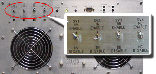
- Inhibit TR faults. Disable the driver module TR fault detection in the PEN cabinet. Ensure that switch SW2 is in the TR DISABLE position.
Figure 1. Driver module front switches
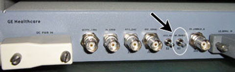
- Place the RF ENABLE S2 switch on the
MNS exciter in the disable (down) position.
Figure 2. RF enable S2 switch location on exciter module
- Remove the transmission cable from RF OUT.
- (For AMT amplifier) Remove cable from J4.
- (For the GEN 1 CPC amplifier, part number 5411744) Remove cable from J3.
- (For the GEN 2 CPC amplifier, part number 5750811) Remove cable from J2.
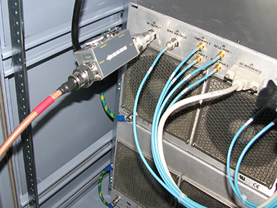
Connect directly to the 35 kW 3.0T RF dummy load. Plug the power supply into the dummy load and the power supply into the 100 VAC service outlet in the cabinet.
Figure 3. Setup for MNS output measurement
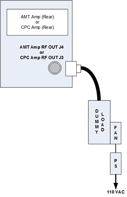
Figure 4. Coupler attached to GEN 1 CPC amplifier (J3)
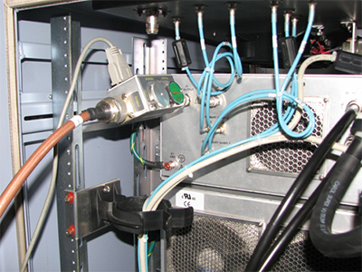
Figure 5. Coupler attached to J2 on GEN 2 power amplifier
- Place the RF ENABLE S2 switch on the exciter in the enable (up) position.
MNS UPM functional check
Procedure
- notice
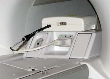
- Connect the MNS 31P T/R switch cabling to the LPCA A connector.
Figure 6. MNS 31P TR switch connection to LPCA
- Landmark on the cradle in the location where the head coil would normally be, and advance to scan.
- From the Common Service Desktop, access the Installation and
Calibration Wizard (ICW):
- For UPM calibration (MNS), select Click here to start this tool.
- For the non-proprietary service tool:
- Select the Calibration tab.
- From the Calibration menu, select UPM Tool > Click here to start this tool.
- For Nuclei select 31P.
- For RF Chain, verify that MNS is selected.
- Select Func Chk.
- Click Start.
The tool takes full control and runs the functional test.
- A prompt displays when the UPM Host Trip test completes. Look in the error log to confirm that the test completed successfully, and that a trip error occurred.
- The UPM status indicates Pass or Fail.
- If the test passes, select Quit from the UPM main window.
- If the test fails, refer to UPM – MNS Setup and Calibration.
 |
Finalization
Procedure
- Place the RF ENABLE S2 switch on the exciter module in the disable (down) position.
- Remove the cables and measurement equipment.
- Reattach the RF OUT cable.
- To re-enable fault detection, set SW2 on the driver module to the enable (up) position.
- Place RF ENABLE S2 on the exciter module to the enable (up) position.
- Complete a TPS reset.
- Any failure requires a re-calibration of the UPM system. See UPM – MNS Setup and Calibration.