
- Discovery MR750 3.0T System Service Methods
- 5690009-2EN Revision 4
- 00000018WIA30FBD030GYZ
- id_123740061.5
- Jul 5, 2019 10:24:08 PM
eXtreme Gradient Amplifier Replacement
Prerequisites
| Required persons | Preliminary requirements | Procedure | Finalization |
|---|---|---|---|
| 1 | 5 minutes | 75 minutes | 5 minutes |
| Item | Quantity | Effectivity | Part number | Manufacturer |
|---|---|---|---|---|
| Hoist Service Kit | 1 | - |
5196226 | - |
| Non-Magnetic Tool Kit (or equivalent) | 1 | - |
5113258 | - |
| Item | Quantity | Effectivity | Part number | Manufacturer |
|---|---|---|---|---|
| Towels | N/A | - | - | - |
| Nitrile Gloves | As needed | - | - | - |
| Item | Quantity | Effectivity | Part number | Manufacturer |
|---|---|---|---|---|
| XGA unit | 1 | systems with XGA units |
See FRU manual. | - |
| XG2 unit | 1 | systems with XG2 units |
See FRU manual. | - |
| ||||||||||||||||||||||||
| Condition | Reference | Effectivity |
|---|---|---|
|
The power in the cabinet needs to be off. Perform LOTO on the PGR cabinet before the XGA unit is replaced. See the MR Service Safety Manual, PN 5452735. | - | - |
|
Before disconnecting any cables on the front of the XGA unit, shut down the PPMP at the HEC. Press ▲ F3 simultaneously to stop the pump. Then switch the PPMP circuit breaker to OFF. | - | - |
About this task
Overview
This procedure explains how to replace an eXtreme Gradient Amplifier (XGA) unit in the PGR cabinet. This unit weighs about 200 pounds so a hoist kit is required. This procedure details the correct way to safely use a hoist kit to remove the XGA unit and replace it with a new XGA.
The system contains either XGA or XG2. These units have the same form factors, but are not interchangeable (a system has either all XGA or all XG2 units). Make sure you order the correct FRU for the system.
This procedure refers to both units as XGA units (except where a distinction needs to be made).
Procedure
- Before setting up the hoist kit, remove the XPS J9 connector
to properly remove the main lifting beam.
Figure 1. Lifting Beam and Connector in PGR Cabinet 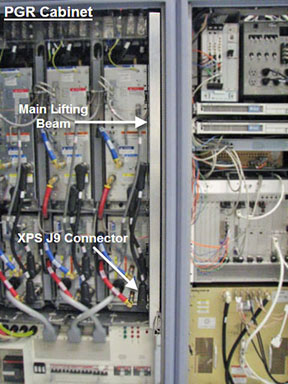
- Note:Turn off the pump breaker, and then disconnect the cables and hoses from the front of the XGA unit. This includes the XPS to XGA power cables, the coolant lines, and the fiber optic cables.
For the next step, wear nitrile gloves. Be prepared to absorb any leakage from the coolant lines with a towel in hand as the line is disconnected.
Note:Do not bend the fiber optic cables. These are very delicate cables and can break easily.
Figure 2. Front of XGA Unit: Cables Connected 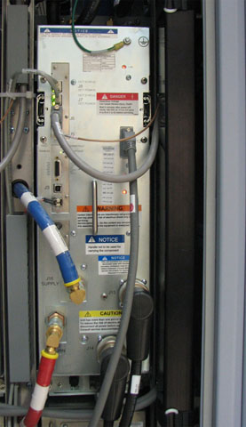
- When the XGA is extended out and you have access to the three
screws, remove the module retaining bracket and set it aside. You
will need this module retaining bracket for the FRU.
Figure 3. Module Retaining Bracket 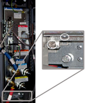 Note:
Note:If replacing the X-axis XGA unit, you may need to remove the PGR cabinet door and lean it to the side of the cabinet. Use tape to secure the free end of the green/yellow ground wire detached from the upper part of left door to the PGR cabinet frame, so it cannot inadvertently contact any of the incoming L1, L2, or L3 AC mains power connections in the terminal strip in the upper left PGR cabinet.
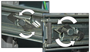
- Remove the nuts on the plus and minus connectors of the gradient
amplifier. Slide it out partially, if necessary. Use two wrenches
to disconnect the cables.
Figure 4. PGR Cabinet - Plus and Minus Connectors 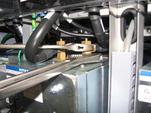
- Place the lifting bracket from the FRU crate on top of the XGA.
The attachment screws are stored on the bracket. Match the four openings
and screw in the lifting bracket.
Use a washer with each attachment screw.
Figure 5. Lifting Bracket 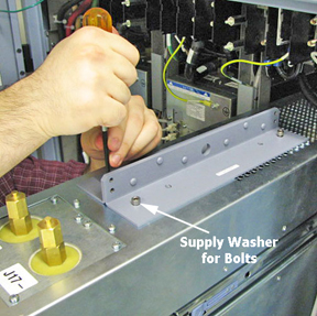
- Hook the winch from the hoist kit to the lifting bracket. Ratchet
the winch to tighten the chain.
Figure 6. XGA Unit Connected to Hoist Kit 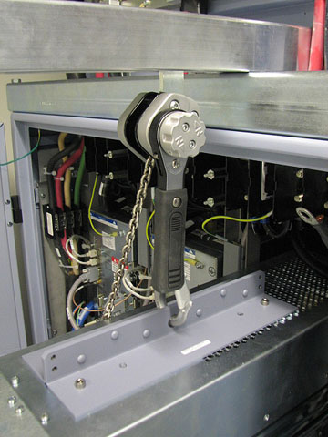 Note:
Note:Make sure the hook is seated in the lifting bracket. If not, the weight can shift and cause harm to the equipment or the engineer.
- With the XGA unit being held by the slide rails and the hoist
kit, it is now secure enough to extend the unit until the slide rails
lock. Press the release tabs in on each side as you pull the unit
out further.
Figure 7. XGA Unit Extended out of Cabinet 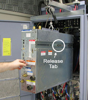
- Push the release mechanism on the back end of the outer slide
rail to release the outer rail. The cabinet rails are a reverse image
of each other.
You may want to use a screwdriver to release the outer slide rail.
Figure 8. Slide Rail Latch Release 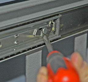
- The FRU is packaged in a wooden crate. Remove the top of the
wooden crate and turn it on its wheels. The XGA unit being removed
can be placed into the top. Roll the top under the XGA unit. Lock
the wheels so that the container does not move.
Figure 9. FRU Package 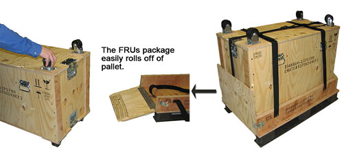
- Bring the new unit to the front of the cabinet. Connect the
slide rails to the new unit.
Figure 10. XGA FRU 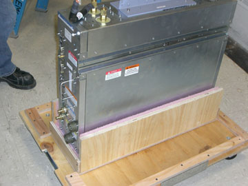
Finalization
- Remove LOTO from the PGR cabinet. See the MR Service Safety Manual, PN 5452735.
- Turn on the PPMP circuit breaker at the HEC. Start the pump by pressing ▲ F3 simultaneously.
- Verify that the pump has started by checking that the drive frequency display shows a value.
- Run the DQA II tool to verify proper gradient polarities and adjust gradient calibration. (See DQA II Tool and Troubleshooting.)
- Recommended: Perform a SaveInfo to capture new gradient calibration values.
- Remove coolant from the XGA unit being returned using the manual coolant removal kit included with the HEC. (See Coolant Draining.)
- Dispose of used towels according to local disposal standards.
- Attach the center of the FRU package to the removed FRU unit base. Then attach the top of the FRU crate to prepare the FRU for return.