
- Discovery MR750 3.0T System Service Methods
- 5690009-2EN Revision 4
- 00000018WIA30990130GYZ
- id_123749391.3
- Jul 9, 2020 10:11:58 AM
Power Strip Replacement
Prerequisites
| Required persons | Preliminary requirements | Procedure | Finalization |
|---|---|---|---|
| 1 | Not Applicable minutes | 90 minutes | 15 minutes |
| Item | Quantity | Effectivity | Part number | Manufacturer |
|---|---|---|---|---|
| Non-magnetic Service Tool Kit | 1 | - |
5112581 | - |
| Hoist Service Kit | 1 | - |
5196226 | - |
| Item | Quantity | Effectivity | Part number | Manufacturer |
|---|---|---|---|---|
| Tie Wraps | As needed (based on drawing) | - | - | - |
| Item | Quantity | Effectivity | Part number | Manufacturer |
|---|---|---|---|---|
| Power Strip | 1 (see FRU manual) | - | - | - |
| XGA and XPS Lifting Bracket | 1 (see FRU manual) | - | - | - |
| Condition | Reference | Effectivity |
|---|---|---|
|
PDU must be powered off. | - | - |
Procedure
Remove the XPS Z unit from the PGR cabinet according to XPS Replacement.Notice Figure 1. XPS Z Unit 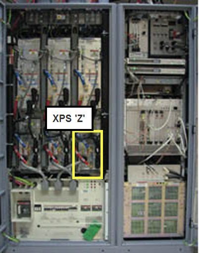
- Unhook the power strip cable plug from the top of the PDU near
the back.
Figure 2. PDU Panel 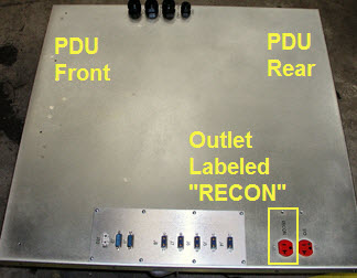
- Unhook the power strip and remove it from the PGR cabinet.
Figure 3. Power Strip in PGR Cabinet 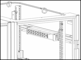
- Install the new power strip and reroute the cable.
Originally, the cable from the power strip was routed toward the back of the PGR cabinet. When replacing the power strip, route the cable toward the front of the cabinet for easier access. In the illustration below, the blue line represents the power strip cabling.
Figure 4. Routing of Power Strip Cabling with Tie Wrap Locations 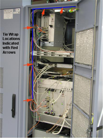
Finalization
Perform a TPS reset.