• Discovery MR750 3.0T System Service Methods
  • 5690009-2EN Revision 4
  • Object ID: 00000018WIA30A75E20GYZ
  • Topic ID: id_13106620 Version: 4.0
  • Date: Feb 21, 2021 9:01:14 PM

Ethernet Switch Replacement

Prerequisites

Table 1. Personnel requirements
Required personsPreliminary requirementsProcedureFinalization
1Not Applicable15 minutesNot Applicable
Table 2. Tools and test equipment
ItemQuantityEffectivityPart numberManufacturer
Standard Service Tool Kit1---
Table 3. Safety
Table 4. Required conditions
ConditionReferenceEffectivity

Turn off all ICNs from the Common Service Desktop. Go to Utilities > Toolbox > VRE > Power Control. Click Power Off for all ICNs.

--

About this task

The Ethernet switch transfers data between the host computer and the PGR cabinet components. The switch is part of the recon subsystem.

Topic ID: id_SL2001580-1061849

Removal of Ethernet Switch

Procedure

  1. Perform LOTO on the PGR PDU/gradient subsystem. See the MR Service Safety Manual, PN 5452735.
  2. Locate the Ethernet switch in the right side of the PGR cabinet, under the ICN.
    Figure 1. Ethernet Switch Location (Typical PGR Cabinet Shown)
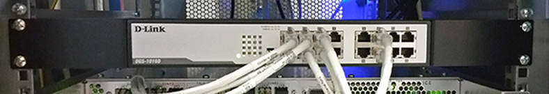
  3. Remove the Ethernet cables from the front of the switch.
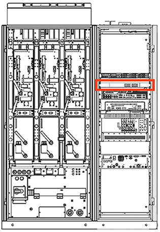
    Figure 2. Ethernet Switch - Front View
  4. Remove the four screws on the front of the switch bracket.
  5. Pull the switch forward. Disconnect the power plug from the rear of the chassis.
  6. If the switch is a returnable FRU, repack the defective switch into the FRU packaging and send it back to its destination.
Topic ID: id_s4-4-1061849

Installation and Power-up

Procedure

  1. Plug in the power cable to the rear of the switch.
  2. Slide the network switch into the original position in the PGR cabinet.
  3. Secure the switch to the cabinet with four screws.
  4. D-link switches with hardware version G3 or H1 on the rating plate have DIP switches on the front. Set the DIP switches according to Table 5.
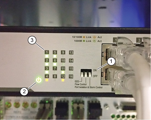
    Figure 3. DIP Switches and LED Indicators
    1DIP switches
    2Power LED
    3Connection LEDs
    Table 5. DIP Switch Settings
    DIP Switch Setting
    EEEOFF
    Flow ControlOFF
    Port Isolation & Storm ControlOFF
  5. Reconnect all Ethernet cables to the ports on front of the switch as marked.
  6. Remove LOTO and power up the unit. See the MR Service Safety Manual, PN 5452735.
  7. Check that the green power LED is on. Also check the connection LEDs for each connected port (solid green indicates a good connection, and flashing green indicates network activity).
Topic ID: id_14953662

Finalization

Procedure

  1. Reboot the host computer.
  2. Perform a verification scan.