- Discovery MR750 3.0T System Service Methods
- 5690009-2EN Revision 4
- 00000018WIA30661130GYZ
- id_123734691.16
- Oct 11, 2021 3:47:38 PM
XRMB Coil Replacement
Prerequisites
| Required persons | Preliminary requirements | Procedure | Finalization |
|---|---|---|---|
| 3 | - | 8 hours | - |
| Item | Quantity | Effectivity | Part number | Manufacturer |
|---|---|---|---|---|
| Extension Cord | 1 | - | - | - |
| Non-absorbent protective clothing (long sleeve shirt and pants), one set per person | 1 | - | - | - |
| PPE: non-magnetic safety shoes, safety glasses, and gloves | 1 set per person | - | - | - |
| Flash PPE | 1 | - | - | - |
| Floor Sign, Warning: Authorized Personnel Only (included in Safety Signage Kit 46-258770G4 | 1 | - | - | - |
| Gradient Coil Insertion Kit | 1 | - |
2164744-6 or later | - |
| HDv Passive Shim Tray Extraction Tool | 1 | - |
5172460 | - |
| Torque Wrench, 8-50 N m Adjustable, non-magnetic | 1 | - | 5534134 or 5534134-2 | - |
| Non-Magnetic Tools Kit | 1 | - |
5112581 | - |
| XRMB Water Removal Pump Kit | 1 | - |
5269683 | - |
| 5 Gallon Bucket | 1 | - |
2239133 | - |
| Air Seal | 1 | - |
5313540 | - |
| Nitrile Gloves | one pair per person | - |
46-194427P400 | - |
| Item | Quantity | Effectivity | Part number | Manufacturer |
|---|---|---|---|---|
| Isopropyl Alcohol, 70%, USFS-200 | 1 | - | - | - |
| Cable Ties | 100 | - | - | - |
| Red Loctite #271 (check expiration date) | 1 | - | - | - |
| Blue Loctite 243 (check expiration date) | 1 | - |
5415261-2 | - |
| Clean Lint-Free Towels (Kimwipes) | AR | - | - | - |
| XRMB Coolant Fluid (approximately 15 gallons of coolant fluid is needed for each XRMB installation) | 4 cartons of 4 – one gallon containers | - |
5174313-4 | - |
| Scotch Brite pad | 1 | - | - | - |
| Black Sharpie pen | 1 | - | - | - |
| Nylon Tie Wraps | As needed | - | - | - |
| ||||||||||||||||||||||||
| Condition | Reference | Effectivity |
|---|---|---|
|
At least one person performing this procedure must have taken training course GEHC-TECH-AMOL-CT530-01_CURR. | - | - |
About this task
Overview
This procedure describes the replacement of the XRMB coil in the 1.5T LCC and 3.0T LCC300 magnets.
This procedure requires disposal of coolant. Inform the customer that coolant disposal is needed and then follow the proper customer coolant disposal procedure.
This procedure requires the gradient coil cable connections to be torqued. Order the torque wrench before you start this procedure.
Getting Started
Procedure
XRMB Coil Water Removal
Procedure
- Note:Turn off both PVC valves in XRMB coolant supply (blue hose) and return line (black hose).
Wear nitrile gloves when performing coolant removal.
Figure 1. Draining Manifold Coolant 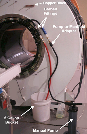
CAUTION Note:To remove the XRMB manifold hoses from the PVC valves, use wrenches to unthread the barb fitting from the PVC valve.Do not cut the barb fittings out of the hoses unless the XRMB coil needs to be drained and returned. This process ensures there will be enough length of hose to reconnect the fitting to the valve.
The connection between hose and fitting is pressure only. To properly remove hose from fitting, carefully cut a slit on the hose but do not damage the water fitting. If coil needs to be drained, carefully make a slit on the manifold hose and slide it off the barb to disconnect the supply manifold from the fitting. Repeat for return line. Retain fitting at the site.
Figure 2. Barb Fitting and Valve 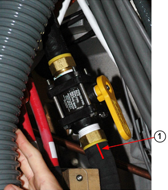
Busbar Assembly Removal
Procedure
- Refer to XRMB Cable Busbar Replacement.
Pull the busbar assembly off the magnet and carefully place it in a safe location.CAUTION - Discard the Nord-Lock washers because they will not be reused.
XRMB Gradient Coil Removal
Procedure
- Obtain the two tube guide roller assemblies (5308402) and XRMB
mounting plates (5161983, 5161985) from the gradient coil insertion
and lift kit shipping crate. Make sure the tube guide roller assemblies
are tightly attached to the XRMB mounting plates.
Figure 3. Roller Assembly and Mounting Plate 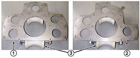
- Install the patient end mounting plate 5161985 (with a tube
guide roller assembly) on the gradient coil patient end and the service
end mounting plate 5161983 (also with a tube guide roller assembly)
on the gradient coil's service end. Use the M10 x 25 stainless steel
hex cap screws (46-318508P20) included in the gradient coil insertion
and lift kit.
Figure 4. Mounting Plates with Roller Assemblies 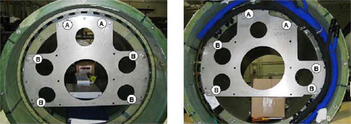
- Adjust the tube support plate assembly's horizontal adjustment
screws until the tube support bearing is centered left-to-right.
Figure 5. Support Plate 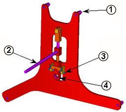
- Attach the tube support plate to the magnet service end using
the 100 mm M10 x 25 stainless steel studs (5303994), stainless steel
M10 nuts and washers included in the gradient coil insertion and lift
kit. Make sure the four extension spacers face towards the magnet
interface ring and nuts are securely tightened.
Figure 6. Support Plate Attached on Interface Ring 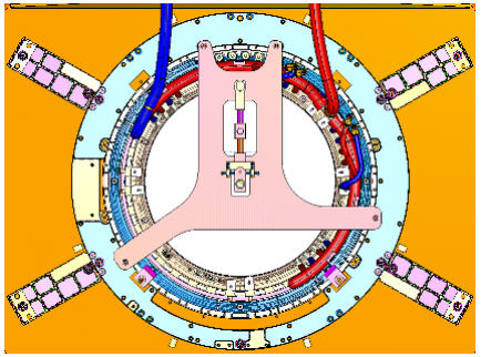
- Remove the 8 brass bolts and G10 washers securing the XRMB wedges
to the front of the magnet.
Figure 7. Removing Brass Bolts 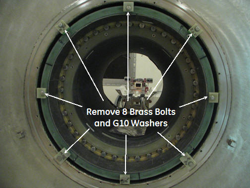
- At the rear end of the magnet, remove four wedges from 45, 90,
270, and 325 degree locations. The three lower wedges (135, 180, and
225 degree) remain on the rear end of the magnet.
Figure 8. Lower Wedges 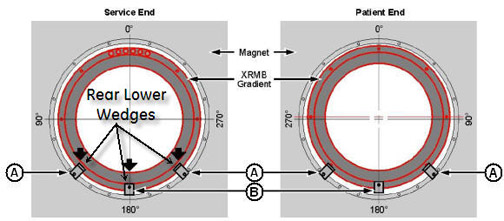
- Maneuver the gradient insertion cart to the patient end of the
magnet. Position the cart in front of the magnet with a gap of at
least 2 inches (50.8 mm) between the cart and the magnet interface
ring. The two-inch gap is required for lower wedges removal.
Figure 9. Two-inch Gap between Magnet and Cart 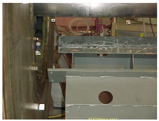
Place the tube jack assembly (5191132) in the cart, and make sure the back of the jack assembly fits properly into the cart.Warning 
Figure 10. Jack Assembly Placement 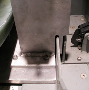
- Obtain the male insertion tube (2284929) and XRMB tube standoff
(5191626).
- Attach the tube standoff to the male insertion tube using the four-inch, 0.375-16 UNC hex socket screw (5303993) included in the gradient coil insertion and lift kit.
- After the standoff is secured to the tube, attach the tube pilot shaft to the standoff.
Figure 11. Attaching Standoff to Insertion Tube 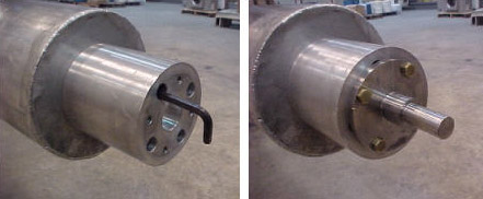
- Remove the PVC shield from the brass thread of the male insertion
tube.
Figure 12. PVC Shield for Brass Thread 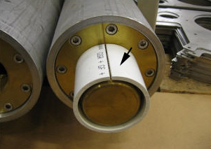
- Slide the male insertion tube, with the standoff attached, through
the tube guide roller assemblies at both sides of the XRMB.
- Push the pilot shaft through the support plate mounting bearing.
- Insert a nonmagnetic safety pin through the hole in the pilot shaft.
Figure 13. Tube Pilot Shaft and Support Plate 
With one person holding the male insertion tube to keep it from rolling, two persons obtain the female insertion tube from the shipping crate and thread the two tubes together. Do not overtighten tube connection, because it may be difficult to remove after gradient coil replacement.Notice Note:Each of the two pieces of the gradient insertion tool weighs less than 35 lb (15.9 kg).
Figure 14. Setting up Insertion Tube Assembly 
Raise the tube jack and the support plate mounting bearing simultaneously to lift the XRMB coil up.Notice Figure 15. Raising XRMB Coil 
Properly secure XRMB coil to the cart.CAUTION Figure 16. Secure the Shipping Bracket 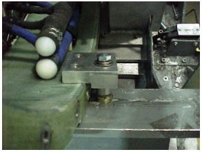
- Obtain the water removal pump kit.
Figure 17. Water Removal Pump Kit 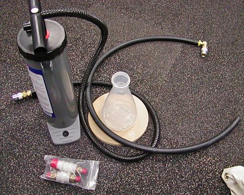
Preparation Before Installing XRMB
Procedure
- Wipe the magnet bore using a clean towel and isopropyl alcohol.Note:
Wear nitrile gloves when performing coolant removal.
Figure 18. Cleaning Magnet Bore 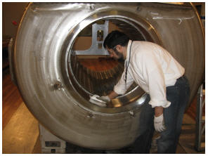
- Remove the shipping brackets securing the XRMB coil to the cart.
Figure 19. XRMB Shipping Bracket - Remove the gradient coil cradle fasteners, two per side, from
the cradle.
Figure 20. Removing Cradle Fastener 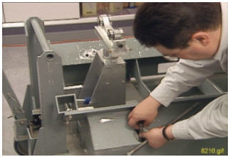
- Obtain the two tube guide roller assemblies (5308402) and XRMB
mounting plates (5161983, 5161985) from the gradient coil insertion
and lift kit shipping crate. Make sure the tube guide roller assemblies
are attached to the XRMB mounting plates.
Figure 21. Roller Assembly and Mounting Plate - Obtain the male insertion tube (2284929) and XRMB tube standoff
(5191626).
- Attach the tube standoff to the male insertion tube using the four-inch, 0.375-16 UNC hex socket screw (5303993) included in the gradient coil insertion and lift kit.
- After the standoff is secured to the tube, attach the tube pilot shaft to the standoff.
Figure 22. Attaching Standoff to Insertion Tube - Remove the PVC shield from the brass thread of the male insertion
tube.
Figure 23. PVC Shield for Brass Thread
Installing XRMB in Magnet
Procedure
- Install the patient end mounting plate 5161985 (with a tube
guide roller assembly) on the gradient coil patient end, and install
the service end mounting plate 5161983 (also with a tube guide roller
assembly) on the gradient coil service end. Use the M10 x 25 stainless
steel hex cap screws (46-318508P20) included in the gradient coil
insertion and lift kit.
Figure 24. Mounting Plates with Roller Assemblies - Attach the 135° and 225° XRMB wedges (5154485) to the
service end magnet flange using one M10 x 30 brass bolt (5110638-64)
and two G10 flat washers (5146169).
- Note:To allow future adjustment, tighten the bolt only enough to secure the wedges.
These two wedges serve as the positioning blocks for XRMB longitudinal (Z axis) alignment.
- Do not apply Loctite at this time.
Figure 25. Service End Positioning Wedges 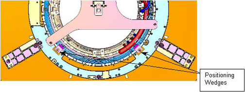
- Maneuver the cart and XRMB coil to the patient end of the magnet.
Position the cart in front of the magnet with a gap of at least 2
inches (50.8 mm) between the cart and the magnet interface ring. (The
two-inch gap is required for lower wedges installation.)
Figure 26. Two-inch Gap between Magnet and Cart - Raise or lower the cradle of the cart as required to align the
two support tub sections (tube support plate at the magnet and gradient
mounting plates at the XRMB) vertically.
Figure 27. Adjusting Cart Height 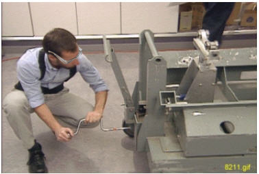
Place the tube jack assembly (5191132) in the cart. Make sure the back of the jack assembly fits properly into the cart.Warning Figure 28. Jack Assembly Placement
With one person holding the male insertion tube to keep it from rolling, two persons obtain the female insertion tube from the shipping crate and thread the two tubes together. Do not overtighten tube connection, because it may be difficult to remove after gradient coil replacement.Notice Figure 29. Insertion of Tube Assembly - Push the complete insertion tube assembly into the magnet bore.
Get the tube pilot shaft close to, but not touching, the tube support
plate.
Figure 30. Complete Insertion Tube Assembly 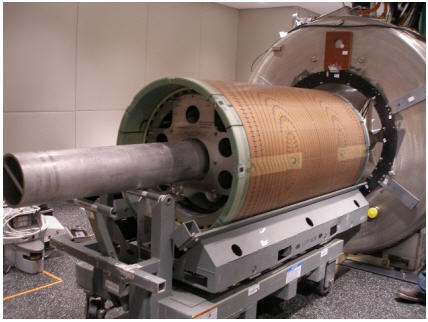
- Push the pilot shaft through the support plate mounting bearing.
Insert a nonmagnetic safety pin through the hole in the pilot shaft.
Figure 31. Tube Pilot Shaft and Support Plate - Raise the tube jack and support plate mounting bearing to lift
the XRMB coil up, keeping the coil approximately level with the magnet
bore while lifting. (You should be able to freely rotate the coil
when it is completely lifted off the cart.)
Figure 32. Raising XRMB Coil - Slowly push the XRMB until stopped by the two positioning wedges
(135° and 225°) already attached to the magnet service end
flange.
- Push the XRMB against the two wedges so that the coil end surface is in good contact with the vertical side of the two wedges.
- If necessary, raise the support plate bearing to gain more clearance between the coil and the lower wedges.
Figure 33. Longitudinal Positioning Wedge 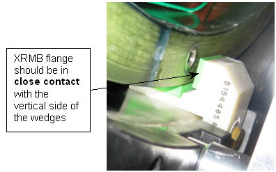
- Slowly rotate the XRMB coil to align its 0° bolt hole with
the slot opening in the radial alignment tool. After aligned, put
the thumbscrew through the alignment tool slot and thread it into
the 0° hole in XRMB coil.
Figure 34. Using Radial Alignment Tool 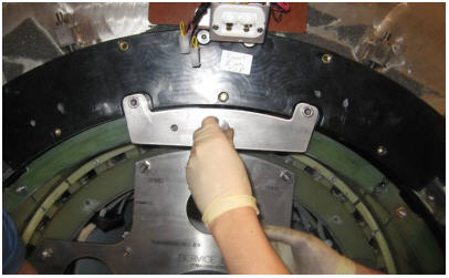
- Apply red Loctite (#271) to the 135° and 225° holes
in the patient end magnet flange. (Shake the Loctite bottle before
using.)
- Attach the 135° and 225° wedge to the magnet flange using one M10 x 30 brass bolt (5110638-64) and two G10 flat washers (5146169).
- Tighten the brass screws firmly to secure the wedges.
Figure 35. Installing Lower Wedges
Slowly lower support plate bearing and tube jack. The full weight of the XRMB is now loaded onto the six lower wedges.Notice Figure 36. Lowering XRMB with Radial Alignment Tool Attached 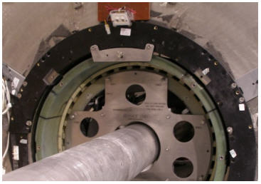
- Use the same method as described in Step 20 and install
the 90° and 270° wedge to both ends of the XRMB coil.
Figure 37. Installing Middle Wedges 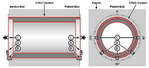
- Use the same method in Step 20 to install
the 45° and 315° wedges to both ends of the magnet.
Figure 38. Installing Upper Wedges 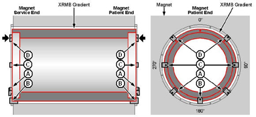
Finalization
Procedure
- For XRMB electrical connection, refer to XRMB Cable Busbar Replacement.
- Place a new Nord-Lock washer over each stud.Note:
The busbar/gradient coil connection is very important. Always use new Nord-Lock washers. Each Nord-Lock washer should be correctly oriented–torque on the nut.
Figure 39. Nord-Lock Washers 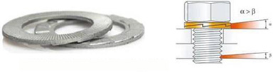
- Put two drops of Loctite 243 on the exposed thread of the stud.
(Shake the Loctite bottle before using.)
Do not get Loctite on the Nord-Lock washer. Hand-tighten the new stainless steel nut on the stud.
Discard the old washers.
Figure 40. Loctite on Stud 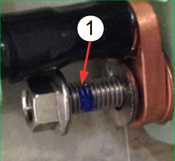
DANGER Notice Notice
Set the torque wrench to 25 ft-lbs or 33.9 Nm. Install 15 mm socket on the extension.Notice Note:Make sure that the arrow on the torque wrench is visible. If the arrow is not visible, the torque wrench will not “click” when the proper torque is reached.
Figure 41. Arrow on Non-magnetic Torque Wrench 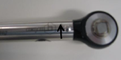
- Using a Sharpie pen, place a line from the base of the stud
to the nut.
Figure 42. Stud and Nut Marked to Show Torque Position 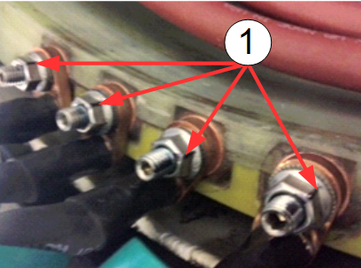
- Place a new Nord-Lock washer over each stud.
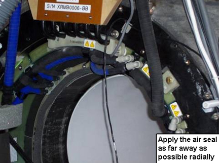
- Apply air seal along the ID on the XRMB endplate (service end only).
Figure 43. Applying Air Seal to XRMB (Service End)