
- Discovery MR750 3.0T System Service Methods
- 5690009-2EN Revision 4
- 00000018WIA30551130GYZ
- id_123738211.6
- Oct 30, 2020 8:53:59 AM
XRMB Cable Busbar Replacement
Prerequisites
| Required persons | Preliminary requirements | Procedure | Finalization |
|---|---|---|---|
| 2 | 3 hours | 5 hours | 3-4 hours hours |
| Item | Quantity | Effectivity | Part number | Manufacturer |
|---|---|---|---|---|
| PPE: non-magnetic safety shoes, safety glasses, and gloves | 1 | - | - | - |
| Arc Flash PPE | 1 | - | - | - |
| Torque Wrench, 8-50 N m Adjustable, non-magnetic | 1 | - | 5534134 or 5534134-2 | - |
| Non-Magnetic Tools | 1 | - |
5112581 | - |
| Item | Quantity | Effectivity | Part number | Manufacturer |
|---|---|---|---|---|
| Blue Loctite 243 (check expiration date) | 1 | - |
5415261-2 | - |
| Alcohol wipes | As needed | - | - | - |
| Scotch Brite pad | 1 | - | - | - |
| Black Sharpie pen | 1 | - | - | - |
| Nylon Tie Wraps | As needed | - | - | - |
| Item | Quantity | Effectivity | Part number | Manufacturer |
|---|---|---|---|---|
| XRMB Cable Busbar | 1 | - |
See FRU Manual | - |
| Busbar Step Gauge (part of FRU) | 1 | - |
See FRU Manual | - |
| ||||||||
| Condition | Reference | Effectivity |
|---|---|---|
|
At least one person performing this procedure must have taken training course GEHC-TECH-AMOL-CT530-01_CURR. | - | - |
About this task
Overview
This procedure describes the replacement or installation process for the eXtreme Resonance Module Revision B (XRMB) busbar (cable version) in the MR750 3.0T magnet.
Getting Started
Procedure
Remove XRMB Gradient Busbar Cables
Procedure
- Remove the two M8x12 mm stainless steel screws and remove the
XRMB busbar safety cover. Do not discard the white flame-retardant
material or the fasteners.
Figure 1. Busbar Safety Cover 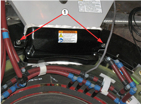
Item Description 1 M8x12 stainless steel screws and M8 nylon flat washers - Remove the six nuts and Nord-Lock washers that are securing
the busbar lugs.
Discard the Nord-Lock washers and stainless steel flange nuts.
Figure 2. Removing Nuts and Nord-Lock Washers 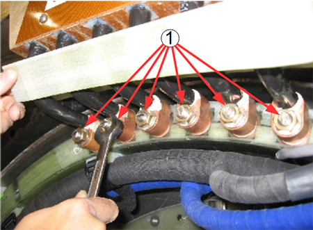
Item Description 1 Six (6) stainless steel nuts and Nord-Lock washers Note:DO NOT remove the clamps on the busbar leads.
- At the top of the busbar, remove the five M6 stainless steel
screws and the clear plastic cover.
Figure 3. Fasteners Holding Clear Plastic Cover 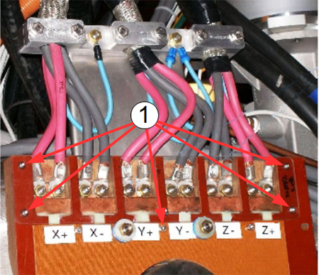
Item Description 1 Five stainless steel screws - Remove the 12 stainless steel nuts and Nord-Lock washers securing
the gradient power cables to the busbar terminals.
Discard the stainless steel nuts and Nord-Lock washers.
Figure 4. Disconnecting Gradient Power Cables at Top of Busbar 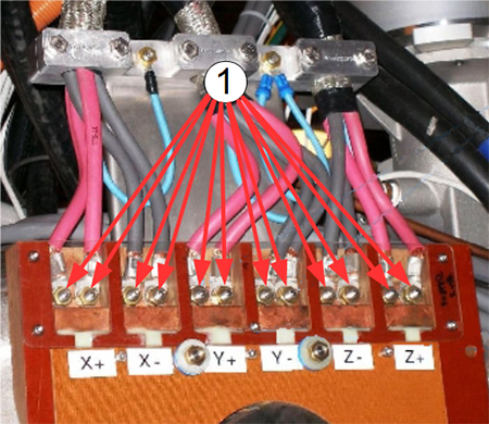
Item Description 1 Twelve stainless steel nuts and Nord-Lock washers
Remove Busbar
Procedure
- Remove the four brass nuts, G10 flat washer, and rubber isolators
securing the busbar assembly to the magnet. Remove the tie-wraps securing
the manifold hoses to the busbar. The busbar may look like either
of the next two pictures.
Figure 5. Busbar Mounting Points 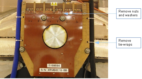
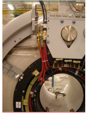
Figure 6. Busbar Removed 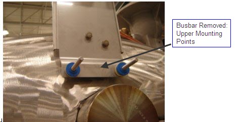
Install New XRMB Busbar
Procedure
- At each busbar support stud, install the large G10 flat washer
(32 mm OD, 5268439) and one rubber
isolator.
Figure 7. Busbar Support Studs (a) and Washer/Rubber Isolators (b) 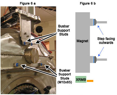
- If absent, install the grounding cable, PN 5189441-2.
Figure 8. Placing Busbar Lugs on Terminal Studs 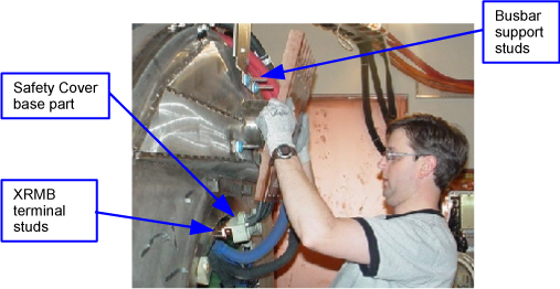
Figure 9. Placing Busbar on Support Studs 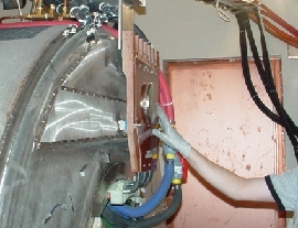
- Ensure that the loose ends of the grounding cables can be accessed
when the busbar is replaced.
Figure 10. Accessible Grounding Cables 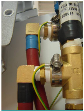
- Gradually tighten the four brass nuts until the height of the
G10 washer surface (front side) reaches 7.2 mm. Use the step gauge
(part of the busbar FRU) to verify the height of the G10 washer. Verify
the busbar lugs are not hung up on the stud threads.Note:
The step gauge is required to prevent stress fractures on the gradient lead terminals.
Figure 11. Checking G10 Washer Height Using Step Gauge 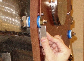
Install Busbar Cables
Procedure
- At the top of the busbar, connect the 12 gradient power cables
to the busbar terminals and secure them using one nut and one Nord-Lock
washer at each of the terminals. Use the torque wrench to tighten
the nuts on the top of the busbar to 25 foot-pounds (33.9 Nm). Read
the following steps prior to using the torque wrench.
Figure 12. Connecting Gradient Power Cables on Top of Gradient Coil - Place a new Nord-Lock washer over each stud.Note:
Observe the following:
-
Always use the new Nord-Lock washers that come with the FRU package. DO NOT reuse the old Nord-Lock washers.
-
Nord-Lock washers consist of two pieces, which are generally glued together. Always use a complete set with two pieces joined together in correct orientation. DO NOT use a separated single piece. If the Nord-Lock washers are separated, or the nuts are untightened, discard the washers and replace them with new Nord-Lock washers only. If new Nord-Lock washers are not available, contact the online center for further instructions.
-
Always shake Loctite bottle before use.
Figure 13. Nord-Lock Washers 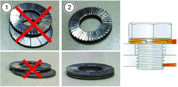
1 Wrong (do not use separated washers) 2 Correct -
- Put two drops of Loctite 243 on the exposed thread of the terminal
stud.
Do not get Loctite on the Nord-Lock washer.
Discard the old stainless steel nuts and washers.
Figure 14. Loctite on Stud 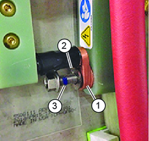
Item Description 1 Bus bar terminal lug 2 Loctite on stud 3 Nord-Lock washer (installed after lug) DANGER Notice Notice
Set the torque wrench to 25 foot-pounds (33.9 Nm). Install 15 mm socket on the extension.Notice Note:Make sure that the arrow on the torque wrench is visible. If the arrow is not visible, the torque wrench will not “click” when the proper torque is reached.
Figure 15. Arrow on Non-magnetic Torque Wrench 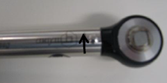
- Using a Sharpie pen, place a line from the base of the stud
to the nut.
Figure 16. Stud and Nut Marked to Show Torque Position 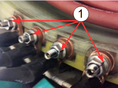
- If the hoses on the left side of the busbar are uneven, use
a Push-Lok Hose, PN 5394470 and Kynar hose barb, PN 46-294167P103
to help bring them to the same length.
Figure 17. Tie-Wrapping Manifold Hoses to Busbar and Applying Ground Wires 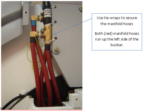
Figure 18. Applying Ground Wires by Hose Clamp to Manifold Fittings Figure 19. Final Position of Manifold Hoses
Finalization
Procedure
- Reposition the rear pedestal.
- Install the magnet enclosure rear end bell. See Rear End Bell Removal and Installation.
- Install the patient bridge. See Bridge and Longitudinal Drive Belt Replacement.
- Replace all covers that were previously removed.
- Remove lockout/tagout (LOTO) to the PGR PDU/gradient subsystem and the RF amplifier in the PEN cabinet. See the MR Service Safety Manual, PN 5452735.
- Execute DQA scan in all three planes to verify proper geometry. See DQA II Tool and Troubleshooting.