
- Discovery MR750 3.0T System Service Methods
- 5690009-2EN Revision 4
- 00000018WIA30C8F030GYZ
- id_123734051.25
- Oct 11, 2021 3:47:51 PM
Replacing XRMw cable busbars
Prerequisites
| Personnel requirements | |||
|---|---|---|---|
| Required persons | Preliminary requirements | Procedure | Finalization |
| 2 | 30 minutes | 5 hours | 2 hours |
| Tools and test equipment | |||
|---|---|---|---|
| Item | Quantity | Part number | Manufacturer |
| Arc Flash PPE | 1 | - | - |
| PPE: non-magnetic safety shoes, safety glasses, and gloves | 1 | - | - |
| Nonmagnetic Titanium Service Tool Kit, Large Set | 1 | 5112581 | - |
| Torque Wrench, 8-50 N m Adjustable, non-magnetic | 1 | 5534134 or 5534134-2 | - |
| Nonmagnetic 80 N m Fixed Torque Wrench Kit | 1 | 5790177 | - |
| Consumables | |||
|---|---|---|---|
| Item | Quantity | Part number | Manufacturer |
| Loctite #243 (check expiration date) | 1 | 5415261-2 | - |
| Alcohol Wipes | As needed | - | - |
| Black Sharpie Pen | 1 | - | - |
| Replacement parts | |||
|---|---|---|---|
| Item | Quantity | Part number | Manufacturer |
| XZ XRMw Busbar | 1 | See FRU Manual | - |
| Y XRMw Busbar | 1 | See FRU Manual | - |
| Required conditions |
|---|
| At least one individual doing this procedure must have taken training course GEHC-TECH-AMOL-CT530-01_CURR. |
| Safety | ||||||||
|---|---|---|---|---|---|---|---|---|
|
Before working in any GE Healthcare MR suite or performing any GE Healthcare service procedure, you must:
If you have any safety concerns at any time, do not begin work or immediately stop work and move to a safe location. Immediately contact your supervisor or site safety officer for instructions on how to proceed. | ||||||||
| ||||||||
About this task
Overview
This procedure describes the replacement or installation process for the eXtreme Resonance Module Revision W (XRMw) busbars.
The system has two busbars: the XZ busbar assembly and the Y busbar assembly. Typically, only one busbar is replaced at one time.
Getting started
Procedure
Removing busbars
About this task
Typically only one busbar is replaced at a time. The removal and installation processes for Y and XZ busbars are the same. If a different instruction is necessary, the instruction is labeled specifically for Y or XZ.
Procedure
- Note: DO NOT remove the clamps on the busbar leads.Note:If you are removing an M10 busbar (no M12 indicator on the busbar face), remove the M10 nuts and Nord-Lock washers that secure the busbar lugs to the coil. If you are removing an M12 busbar (M12 indicator on the busbar face), remove the M12 SmartBolts and Nord-Lock washers that secure the busbar lugs to the coil. Slide the busbar terminal lugs off of the studs at the coil.
Never use the nonmagnetic torque wrench to loosen connections, the torque wrench has a range of 10 - 50 N*m ( 8 – 35lbf*ft), removing Nord-Lock© or Spiralock© threads may exceed the limit of this wrench and destroy the ratchet components.
Figure 2. M12 indicator 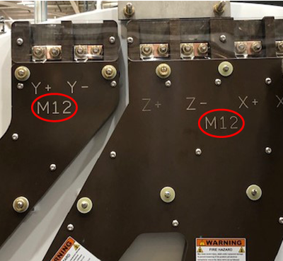
Discard the Nord-Lock washers and stainless steel flange nuts or SmartBolts.
Installing busbars
About this task
Typically only one busbar is replaced at a time. The removal and installation procedure for Y and XZ busbars are the same. If a different instruction is necessary, the instruction is labeled specifically for Y or XZ.
Procedure
- Note: Make sure of the following:Place a new Nord-Lock washer over the stud. Put two drops of Loctite 243 on the exposed thread.
- Always use the new Nord-Lock washers that come with the FRU package. DO NOT reuse the old Nord-Lock washers.
- Nord-Lock washers consist of two pieces, which are generally glued together. Always use a complete set with two pieces joined together in the correct orientation. DO NOT use a separated single piece. If the Nord-Lock washers are separated, or the nuts are untightened, discard the washers and replace them with new Nord-Lock washers only. If new Nord-Lock washers are not available, contact the online center for further instructions.
Figure 9. Nord-Lock washers 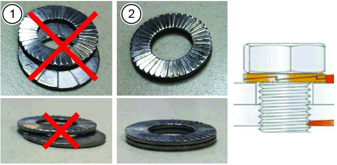
1 Wrong (do not use separated washers) 2 Correct - Always shake the Loctite bottle before use.
Note: If there is no stud (M12 connection), do not apply Loctite to the Smartbolts.Do not get Loctite on the Nord-Lock washer. Hand-tighten the nut.
Discard the old washers.
DANGER Notice Notice
Set the torque wrench appropriately:Notice - (For M10 nut/stud configuration) Set the torque wrench to 25 ft-lbs or 33.9 Nm. Install a 15 mm socket on the extension.
- (For M12 SmartBolt configuration) Set the torque wrench to 59 ft-lbs or 80 Nm. Install a 17mm socket on the extension.
Note: Make sure that the arrow on the torque wrench is visible. If the arrow is not visible, the torque wrench will not “click” when the proper torque is reached.Figure 10. Arrow on nonmagnetic torque wrench 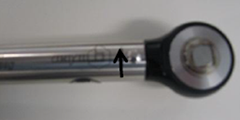
- (For M10 nut/stud configuration) Using a Sharpie pen, place a line from the base of the stud to the nut.
Figure 11. SmartBolt 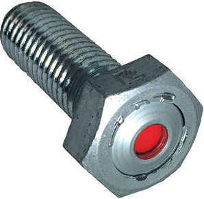
A red indicator means the SmartBolt is not torqued, as shown above; a black indicator means the SmartBolt is torqued.
Figure 12. Stud and nut or SmartBolt marked to show torque position 1 Black line on nut and stud to show torque position. Repeat this process for all terminal connections.
- At the top of the busbar, install the plastic cover with two screws to the busbar.
- (For Y busbar) Two screws hold the plastic cover on the Y busbar.
- (For XZ busbar) Three screws hold the plastic cover to the XZ busbar.
Always make sure that the stud extends beyond the end of the nut.
Figure 13. Installation sequence of terminal 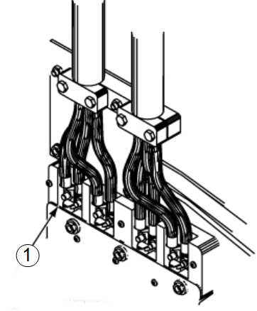
1 Sequence for installing fasteners:
- Power cable lug
- Nord-Lock washer
- Nut
Finalization
Procedure
- Install the rear end bell enclosure. See Rear End Bell Removal and Installation.
- Install the rear pedestal.
- Install the patient bridge. See Bridge and Longitudinal Drive Belt Replacement.
- Replace all covers that were previously removed.
- Remove lockout/tagout to turn the system ON. Refer to the MR Service Safety Manual (5452735).
- Do DQA II to verify proper geometry. See DQA II Tool and Troubleshooting.