
- Discovery MR750w and SIGNA™ Architect T 3.0T System Service Methods
- 5690002-2EN Revision 4
- 00000018WIA30291130GYZ
- id_152711155.0
- Nov 2, 2021 1:35:59 PM
Dual drive quadrature tool
Personnel requirements
| Required persons | Preliminary requirements | Procedure | Finalization |
|---|---|---|---|
| 1 | Not Applicable | 45 mins | 5 mins |
Tools and test equipment
| Item | Qty | Effectivity | Part# | Manufacturer |
|---|---|---|---|---|
| Body Loader with Sphere Phantom | 1 | 2371511 |
- | |
| Service Filler Panel | 2 | For curved tables | 5344577 |
- |
| Coil phantom Foam Support for Flat Table (GEM) | 1 | For flat (GEM) tables | 5404900 |
- |
| Head TLT Sphere for 3.0T (Pink Solution) | 1 | - | 2359877 |
- |
| Pad for Head Sphere | 1 | - | 46-328383P1 |
- |
| Curved Adapter Panel for Flat Table (GEM) | 1 | For flat (GEM) tables | 5395828 | - |
| Item | Qty | Effectivity | Part# | Manufacturer |
|---|---|---|---|---|
|
Body loader with sphere phantom |
1 | 2371511 |
Dual drive quadrature tool overview
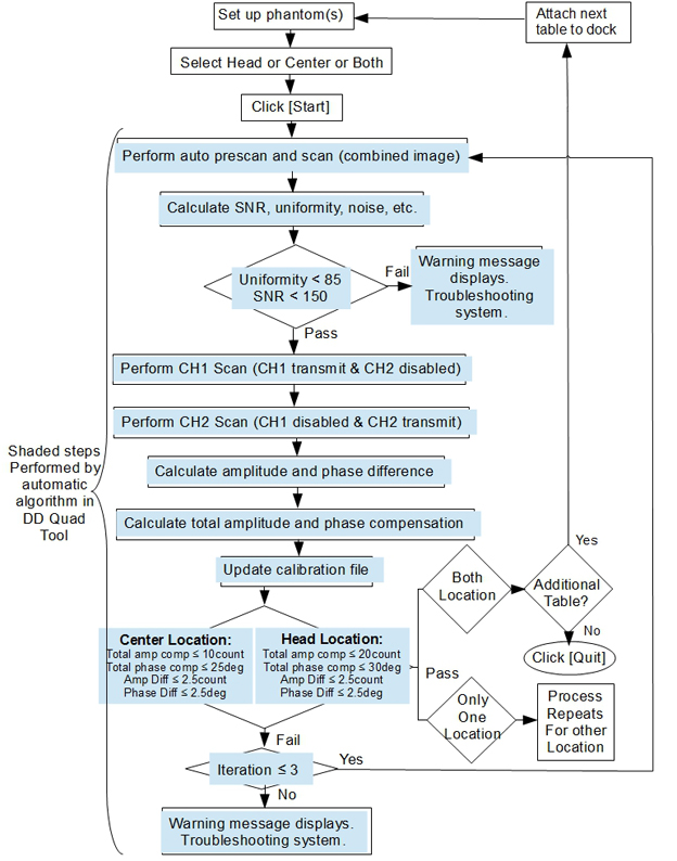
A dual drive system has two transmit channels. The dual drive (DD) quadrature tool is used to compensate for the amplitude and phase differences in the transmit channels. Amplitude and phase differences between the two channels can begin at the exciter and be carried through to the body coil transmit (the end of the imaging chain). Those differences can also be introduced at any of the intermediate passive components.
The dual drive quadrature tool performs axial scans in three modes.
- Combined mode
- CH1 transmit, CH2 disabled
- CH2 transmit, CH1 disabled
The dual drive quadrature tool calculates amplitude difference between the CH1 and CH2 channels. It also calculates phase difference between the CH1 and CH2 channels. It then updates the system calibration file with the cumulative compensation required.
Test mode without calibration is provided.
MR750w performs calibration in head and center locations.
MR750 only calibrates in center location.
Compensation scans must be done in the head area of the cradle in addition to the center area of the cradle. The tool allows for both scans to be executed in a single iteration of the tool. Also, the dual drive quadrature calibration MUST be done on all GEM tables that will be used with the system. The system tracks the coil ID and serial numbers of each GEM PA coil and prevents scanning with any GEM table containing a GEM PA coil that did not complete the dual drive quadrature calibration. In addition, if the site has one or more curved tables, dual drive quadrature calibration must also be done on one of the curved tables.
If the site has a non-electrical table option (for example, FUS or Surgical Suite), and does not have a GE curved table,Non-electrical table option must be completed to use the non-electrical table.
The procedure can be run in non-proprietary mode and proprietary mode. Non-proprietary mode is accessed from the MR Service Desktop. Proprietary mode is accessed through the calibration wizard.
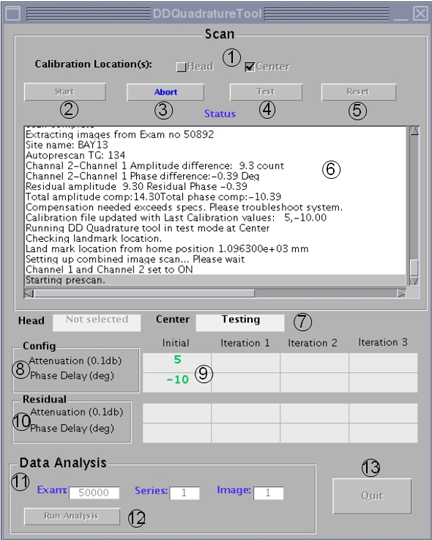
| Locator | Item | Description |
| 1 | Calibration Location | Select Head or Center or both. |
| 2 | Start | Click Start to start the calibration. |
| 3 | Abort | Click Abort to abort the calibration process. |
| 4 | Test | Click Test to confirm the test results. The calibration file is not updated. |
| 5 | Reset | Reset the initial value to Default(0,0) or the last calibration value. |
| 6 | Status | Displays the dialogue of the procedure. |
| 7 | Head/Center | Displays calibration/test status of the location. |
| 8 | Config | The value is the calibration file and is updated when a successful calibration is completed. |
| 9 | Initial | Initial value before adjustment. |
| 10 | Residual | Residual after the compensation is applied. |
| 11 | Data Analysis | This mode allows the user to re-analyze scanned data acquired with the dual drive quadrature tool. It includes the combined image exam, series, image number, and prompts the user for the Pfiles created by the individual channel scans. This mode does not update the calibration file. This mode can also be used for troubleshooting because it provides some freedom in how the data is acquired. |
| 12 | Run Analysis | Click Run Analysis to initiate the data analysis process. |
| 13 | Quit | Quits the dual drive quadrature tool. |
Before starting the dual drive quadrature tool procedure
If you are calibrating multiple tables, follow these steps:
- Complete successful table calibration.
- Exit the dual drive quadrature tool by selecting Quit.
- Connect the next table to be calibrated.
- Restart the dual drive quadrature tool and repeat the steps above.
If you try to calibrate multiple tables without exiting the tool, you will see an error message.
If the site has a non-electrical table option (for example, FUS or Surgical Suite) and does not have a GE curved table,Non-electrical table option must be completed to use the non-electrical table.
If you are doing only the center location scan, proceed to Setting up for center location scan.
Setting up for head only or both head and center scan
Procedure
- If setting up for the head only scan, position the head sphere phantom as shown in the following illustration.
For GEM (flat) table:
- Place the pad toward the head of the table.
- Position the head sphere phantom on the pad.
For curved table:
- Install the service filler panels under each of the two cradle panels.
- Place the pad toward the head of the table.
- Position the head sphere phantom on the pad.
Figure 3. Positioning for head location (phantom and pad) 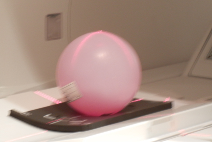
- From the home position, move the cradle in so that the in-room monitor shows 315 mm. Turn on the alignment lights by pressing the Alignment button on the magnet enclosure.
Figure 4. Buttons on magnet enclosure 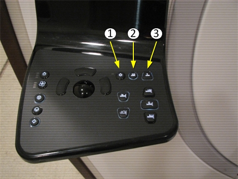
Item Description 1 Alignment lights button 2 Landmark button 3 Advance to scan button - Adjust the head phantom location where the laser light cross hairs line up on the center of the phantom. Press the Landmark button.
- If scanning only the head location, press Advance to scan. Proceed to Accessing dual drive quadrature tool.
- If scanning both head and center locations, move the cradle in an additional 765 mm.Align the body loader and sphere on the center of the laser light cross hairs. Press Advance to scan, and proceed to Accessing dual drive quadrature tool.
Figure 5. Positioning for center location (body loader and phantom) 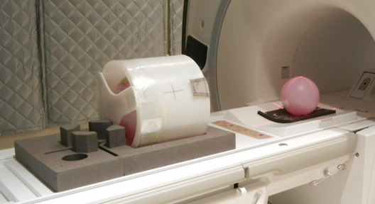
Notice
Setting up for center location scan
Procedure
- Turn on the alignment lights by pressing the Alignment button on the magnet enclosure.
Figure 6. Buttons on magnet enclosure Item Description 1 Alignment lights button 2 Landmark button 3 Advance to scan button
Accessing dual drive quadrature tool
Procedure
- (For non-proprietary mode) Select Calibration > Calibration Tools > Dual Drive Quadrature, then Click here to start the tool.
- (For proprietary mode) Run the Calibration Wizard, and select Dual Drive Quadrature.
Running dual drive quadrature tool
Procedure
- Click Start for the first iteration.
Scan and analysis begin. It takes about 6 minutes.
Figure 7. Dual drive quadrature tool GUI - (For passed) Click Quit to complete the calibration. Proceed to Finalization.
Figure 8. Pass case 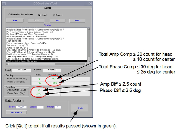
- (For failed) If the head location fails, the calibration scan stops. If you selected head and center locations to be done together, you must manually start the center location calibration scan.
Figure 9. Fail case (at first iteration) 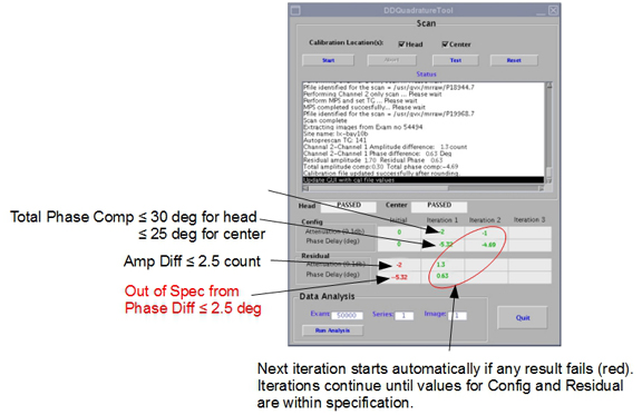
Table 4. Specifications for dual drive quadrature calibration Phase or Magnitude Value Head location phase 30 degrees Head location magnitude 20 counts (2.0 dB) Center location phase 25 degrees
Center location magnitude 10 counts (1.0 dB)
Quadrature calibration troubleshooting
MR750w systems support a dual drive RF transmit chain, referred to as channel 1 and channel 2.
The signals for both channels originate from the exciter and are sent to the dual drive RF amplifier, where they are amplified to a maximum of 15 kW per channel for body coil mode only. The RF output riding on the T/R pulse is sent to the dual transmit receive switch (DTRSW) and then to the RF body coil. Because there are two RF signals, this redundancy can be used to troubleshoot the RF output.
For information on running the calibration tool, and for specification values, see Dual drive quadrature tool.
For more information, see:
- For information on how dual drive works, see Dual Drive Theory.
- For information on dynamic disable and T/R pulse errors, see T/R and DD Troubleshooting .
| Warning | |
|---|---|
| Warning | |
|---|---|
| Warning | |
|---|---|
Go through the table twice–once for head location and once for center location.
| Question/Problem | Possible Causes | Actions |
| Does the tool fail to run? |
|
|
|
Does the tool fail due to low SNR? (See Viewing log file) |
|
|
| Does the tool fail due to low uniformity? (See Viewing log file |
|
|
|
Does the tool fail due to high TG? (See Viewing log file) |
|
See the appropriate troubleshooting below. |
| Do the results fail? (not converge) |
|
|
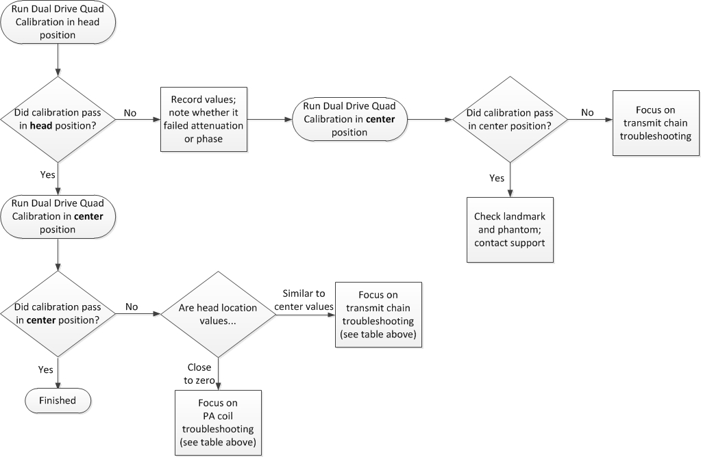
Dual drive quadrature calibration failure information
Generic error message
The Dual Drive Quadrature Calibration tool generates the following message when it detects an error that prevents it from executing.
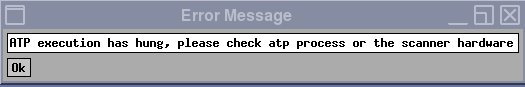
Because the tool reports this generic error message for a variety of reasons, it is important to check the error log when this error message is displayed. Three conditions that can generate this error message are Scan Door Open, No Signal, or Low Signal.
If the Dual Drive Quadrature Calibration tool found a Low Signal condition, the tool generates the following error message in the error log.
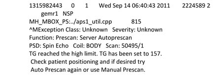
The above faults may not be associated with the Dual Drive Quadrature Calibration tool. For example, a poorly calibrated RF amplifier could cause a low signal condition.
Viewing log file
The Dual Drive Quadrature Calibration tool generates a log file. However, there is no GUI viewer for it. To view calibration log files, open a C Shell and type:
>cd /usr/g/service/log/systools/
ls -al QuadCal*
The files are listed. Quadrature calibration file names start with QuadCal and end with .dat, and contain the coil ID for the system’s PA coil.
QuadCal_Y_30T0GEM0E0FLAT0TABLE0P2P3P40xxxx_GEMSsiggjNFhn3pJ6xvsAqJoBQvFU0qb_630000001301a00f.dat
An example log file is below:
Iteration 1
Checking landmark location.
Land mark location from home position 1.100100e+03 mm
Setting up combined image scan... Please wait
TG Window = 53
Channel 1 and Channel 2 set to ON
Auto prescan successful...
Phantom offsets (mm) X:L 8, Y:A 24, Z=I -1
Completed scanning for combined image
Last exam: 53651
Extracting image 1 in Exam 53651 complete
Combined image SNR 136.41, Uniformity 87.26
Combined image SNR 136.41 lesser then required SNR 160.00
Compensation PASS
Difference PASS
The log file provides errors for particular issues. For example:
Combined image SNR 136.41 lesser then required SNR 160.00
indicates that test failed due to low SNR.
Compensation PASS
indicates if channel to channel attenuation passed or failed.
Difference PASS
indicates if channel to channel phase difference passed or failed.
Dual drive quadrature calibration failures due to magnitude: low Signal on one channel
Swapping the RF transmit or receive cables does not cause hardware damage, but it does create a situation known as reverse quadrature. When this occurs, the combined image has a low signal. To determine if this is the problem, generate the three images using the Dual Drive Quadrature Calibration tool.
The illustration below shows the results of a system that has proper quadrature and the proper signal strength from both channel 1 and channel 2.
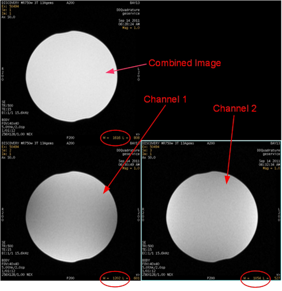
Values are approximate and may vary if system gain was not previously executed. The ratio between the combined scan and the single channel scan is approximately 1.41 : 1. If the value for the combined image is 1400, the value for the single channel scans should be approximately 1000.
| Item | Quantity | Part Number |
| Body TLT sphere phantom (pink solution) | 1 | 2360025 |
| Body TLT short loader | 1 | 2360037 |
- Place the body TLT sphere and loader on the table. If you are using a flat (GEM) table, use the foam holder to contain the phantom.
- Landmark the phantom and drive it into the magnet bore.
- Click New Patient to set up for a scan.
- Under Protocol, select Service. Then select DDquadrature.
Figure 14. Protocol selector screen 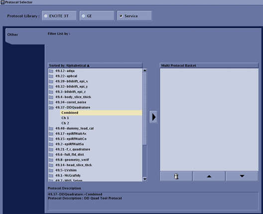
-
Set up and scan the combined image. DO NOT perform Auto Prescan. Perform Manual Prescan and set the values to:
- TG = 150
- R1 = 11
- R2 = 14
- After scanning the combined image, removed the RF input cable from RF amplifier channel 2 by disconnecting J21. Leave channel 1 (J14) connected. Repeat the same scan WITHOUT changing any of the values for TG, R1, or R2. This linear scan uses only channel 1.
- When the image for channel 1 is complete, reconnect J21 (channel 2 input) and disconnect J14 (channel 1 input). Repeat the same scan WITHOUT changing any of the values for TG, R1, or R2. This linear scan uses only channel 2.
- Now there are three images. Review them. Figure 13 shows the results for a system that has proper quadrature and the proper signal strength from both channel 1 and channel 2. Use Table 7 to troubleshoot your images.
Table 7. Troubleshooting Scan Images Scan result Problem Resolution If the combined image has a weaker signal than either image from the single channels: The system could be transmitting in reverse quadrature. Somewhere in the RF transmit chain, the channel 1 and channel 2 cables are swapped. Locate the swapped cables and connect them correctly. Cables between DTRSW and the body coil must always be in the correct locations, or the body receive signal will be poor. Swapping channel 1 and channel 2 cables somewhere else in the transmit chain will not restore the body receive signal quality to normal.
If the signal for one of the channel images is lower than the other channel: There could be low or no RF signal from one of the channels. Check the RF output using: - RF Amp Power Check tool
or
- Power Measurement Kit (see Body and Head Maximum Power Setup and Calibration).
- RF Amp Power Check tool
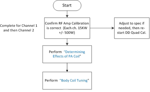
- If all the cables and the RF outputs are correct and the source cannot be determined by visual inspection of the images, proceed to Determining Effects of PA Coil.
Determining Effects of PA Coil
The presence of the PA coil in the bore affects the results of DD Quadrature Calibration. Both the magnitude and the phase are changed when the PA coil is in the magnet bore (compared to being out of the magnet bore). SNR aborted by DD Quadrature Calibration should not change.
To check the interaction of the PA coil, scan with the PA coil and cradle out of the bore as described below.
- Landmark the phantom as usual. Mark the phantom location on the body coil with tape.
- Press the emergency release on the cradle and pull the cradle back onto the table. Manually position the phantom on the panel or pad so it is horizontally and vertically centered in the location on the bridge.
Figure 15. Phantom position in bore 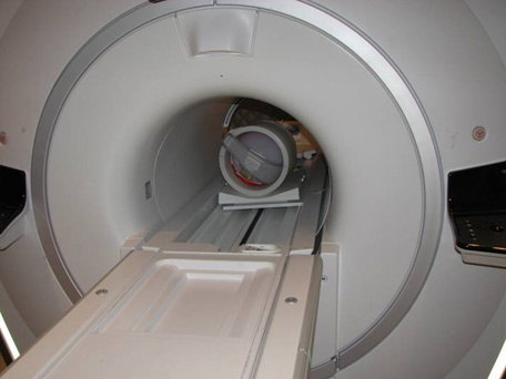
- Apply tape to push in on the cradle sensor, which will permit scanning with the cradle unlatched from the LPCA.
Figure 16. Tape position for cradle sensor 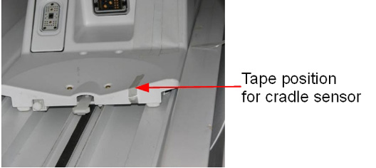
- In the DD Quadrature Calibration Tool, verify that only the center location is selected, and then run the calibration tool, Dual drive quadrature tool.
- Compare the results of DD Quadrature Calibration when the PA coil is in the bore with the results when the PA coil is out of the bore.
In a good working system the difference in attenuation and phase results between the PA coil in bore and out of bore are small. We have typically observed a -0.5 dB (or -5 count) decrease in the magnitude and a -5 decrease in phase when comparing results with the PA in bore to results with PA removed from bore.
- If DD Quadrature Calibration fails only when the GEM PA coil is in the bore due to low SNR, replace the GEM PA coil. Otherwise, perform the next troubleshooting action.
Phase Troubleshooting
This section is designed to help the FE locate the largest contributor of phase shift in the transmit chain. This is done by swapping cables and hardware between the DTX1 exciter and the RF body coil, and checking for the largest change in phase after every swap. A change in polarity after a cable swap indicates that you have reached one of the cables contributing a majority of the phase shift. Ideally, each channel 1 and 2 transmit chain section should contribute almost no phase shift. In a normal system, swapping channel 1 and 2 cables in any location results in almost no change in phase polarity.
- Using a normal system configuration, perform quadrature calibration in Test mode and record the initial residual phase value and polarity as result A.
- In Figure 17, The circled numbers show where to swap cables. The numbers progress from the most-likely to the least-likely problem area.
For each action, swap all cable connections identified with swap symbol <—>. For example, for action 1, swap the channel 1 and channel 2 cables (swap J9 and J11 on the PGR cabinet, and swap J22 and J15 on the PEN cabinet).
In each action (except action 5) each end of the cable is swapped so that the entire section of cable is relocated to the other transmit line. Action 5, however, only swaps the cable ends connecting to the DTRSW.
Figure 17. Phase troubleshooting 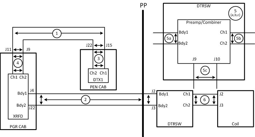
- Starting with action 1, swap both ends of cables as shown to relocate the entire cable onto the other transmit line. (For action 5, swap cables only at the DTRSW.)
For action 2, try the cable ends at the PGR and DTRSW first. If the problem continues, try the cable ends at the pen panel.
- After swapping the cables, repeat quadrature calibration in Test mode for the given action, and record the new initial residual phase value and polarity as result B.
- Compare the values recorded as result A and result B:
- If the polarities are the same, neither of the cables are the cause of phase failure. Return the cables to the normal positions and repeat the steps above with the next numbered action, until you find the problem or all actions are done.
- If the polarities are different and this is action 5, stop and replace the DTRSW because it is the source of most of the additional phase.
- If the polarities are different and result A is positive, then most of the additional phase is in the channel 2 transmit cable that was swapped. Inspect the cable and confirm that it is the correct cable for the system. Reseat the cable.
- If the polarities are different and result A is negative, then most of the additional phase is in the channel 1 transmit cable that was swapped. Inspect the cable and confirm that it is the correct cable for the system. Reseat the cable.
- If the situation remains unchanged, the only items left are the DTX1 exciter and the body coil. Contact support before continuing.
Magnitude troubleshooting
Cable swapping can also be utilized to isolate magnitude issues with dual drive systems. The magnitude change between channels should not vary more than 5 counts when the RF transmit cables are swapped. The following process tests the entire transmit chain from the output of the exciter to the output of the DTRSW. The only cables that are not be tested are the cables that run between the DTRSW and the body coil.
- Using a normal system configuration, perform quadrature calibration in Test mode and record the initial residual magnitude value and polarity as result A.
- Swap cables between exciter outputs at J12 and J13 at the exciter, and swap cables between J2 and J3 at the DTRSW.
Figure 18. Magnitude troubleshooting 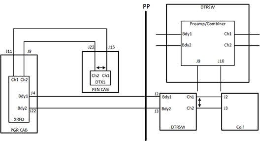
- After swapping the cables, repeat quadrature calibration in Test mode for the given action, and record the new initial residual magnitude value and polarity as result B.
- Compare the results. If there is a 5 count difference between the two magnitude values, the transmit chain is contributing to the magnitude error.
Using RFA tool to troubleshoot DD quadrature calibration failures
The RFA Loopback Test can be used to measure deviations in magnitude and phase for channel 1 and channel 2 anywhere in the transmit chain between the DTX exciter and the DTRSW. It cannot be used to accurately measure magnitude and phase for channel 1 and channel 2 from the RF body coil.
It is recommended that RFA be executed first at the output of the DTRSW. This will determine if an issue is either with the system electronics leading up to the DTRSW or if the issue is with the body coil. If the failure is determined to be before the DTRSW, RFA can be used to isolate the failure location.
| Warning | |
|---|---|
Tools and test equipment
| Item | Quantity | Part Number |
| Power measurement kit | 1 | 5307511 |
| SST kit | 1 | 5110731-4 |
| 70 dB, with 10 dB step, attenuator (from 3.0T Grafidy kit, part 2386042) | 1 | 46-255838P2 |
Determining “Hot” channel
Either channel 1 or channel 2 could be the “hot” channel (that is, the channel with largest gain). First determine which channel is the hot, then use that channel to set the initial value of the attenuators. If you use the wrong channel to set up the attenuators, the values may be over-ranged, causing inaccurate results.
To determine which channel has larger gain, examine the results from the DD Quadrature Calibration tool. The channel with the larger attenuation value reported in the calibration tool is the hot channel.
Based on which channel is hot, follow the correct instructions below (Running RFA: channel 1 First or Running RFA: Channel 2 First).
Running RFA: channel 1 First
Complete these steps if you have determined that channel 1 is the hot channel (see Determining “Hot” channel). If channel 2 is the hot channel, refer instead to Running RFA: Channel 2 First.
Setup for channel 1
See Setup for Channel 2 for information on setting up channel 2.
- Before running RFA, zero out any residual values in the DD Quadrature tool as follows:
- On the Common Service Desktop, select Calibration then select DD Quadrature Calibration.
- Select Reset.
- Select Defaults (0,0).
- Exit the DD Quadrature tool.
- Ensure that the system is idle, and remove all portable coils from the bore.
- Place the body TLT sphere and loader on the table. If you are using a GEM (flat) table, use the foam holder to contain the phantom.
- Landmark the phantom.
-
On the driver module in the PEN cabinet, set switch 2 (SW2) to TR DISABLE and SW3 to DD DISABLE.
Figure 19. Setting TR and DD Disable 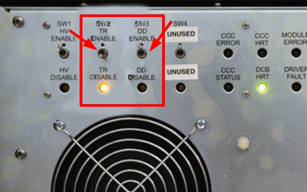
-
On the exciter/ref clock module located in the PEN cabinet, set the RF Enb switch to down (Disable).
Figure 20. Exciter/Ref Clock Module 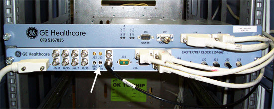
-
To gather data from the first channel, set up the test configuration using the diagram and steps below.
Figure 21. DTRSW Troubleshooting for Channel 1 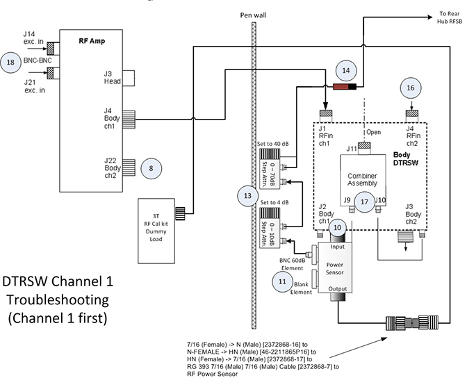
-
Disconnect the Ch2 transmit cable from the RF amplifier at J22. Connect the cable from J22 to the 3.0T 35 kW (50Ω) dummy load.
-
Disconnect J7 and J8 at DTRSW. Leave cables disconnected.
-
Remove Ch1 RF output cable to body coil from the DTRSW at J2. Leave the cable disconnected.
-
Place a 60 dB BNC element, labeled 2372868-22, into the Forward port of the 5010G RF power sensor. Install a metal element blank or any other sense element into the open port labeled Reflected on the power sensor. The Reflected port is not measured, so the type of element used to fill this port is not critical.
-
Connect the power sensor to J2 of the DTRSW.
-
Install two adjustable attenuators in series with the 60 dB element in the RF power sensor. Set up the attenuators. Set the 1 dB step attenuator to 4 dB, and the 10 dB step attenuator to 40 dB. Total additional attenuation provided by the step attenuators should be 44 dB.
-
Remove the body receive cable from the preamp combiner at J11. Connect a DC block at the end of this cable and connect the other end of the DC block to the step attenuator.
-
Disconnect the Ch2 RF transmit to body coil cable at J3 of the DTRSW. Leave the cable disconnected.
-
Remove the Ch2 RF transmit cable at J4 of the DTRSW. Connect this end to the output side of the RF power sensor using the RF cable from the SST kit and the two RF connectors from the RF power measurement kit.
Table 9. Required Connectors and Cables Part Name Part Number Kit Name RF Connector, 7/16 (Female) -> N (Male) 2372868-16 3.0T RF Power Measurement Kit RF Connector, N-FEMALE -> HN (Male) 46-2211865P16 SST Kit RF Connector, HN (Female) -> 7/16 (Male) 2372868-17 3.0T RF Power Measurement Kit -
Disconnect the input cables to the preamp combiner at J9 and J10.
-
Disconnect J21 cable at the RF amplifier. Leave cable disconnected.
Data Analysis
| Notice | |
|---|---|
-
On the exciter/ref clock module located in the PEN cabinet, set the RF Enb switch to Enable (UP).
-
Insert the service key into the PC.
-
From the Common Service Desktop, select the Image Quality tab, and then select RFA.
-
Set Loopback Mode to Body Dummy, RF Pulse Type to Ascending, Dual Drive Output to Ch1 output only looped back and Disable Ch2 exciter output.
-
For channel 1, set Dual Drive Output to Ch1 output only looped back and Disable Ch2 exciter output.
-
For channel 2, set Dual Drive Output to Ch2 output only looped back and Disable Ch1 exciter output.
Figure 22. RF Analysis Tool Menu 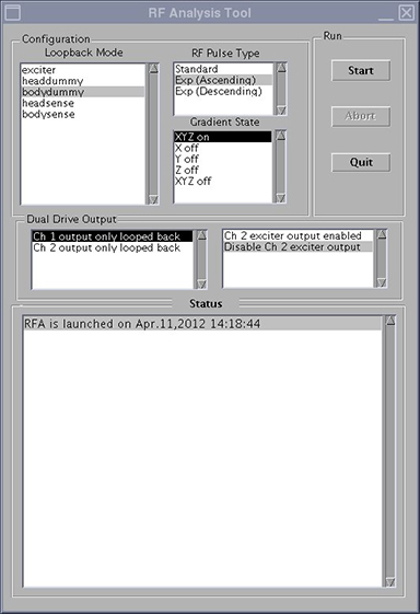
-
-
Click Start.
Note: SVAT errors usually indicate a setup problem such as landmark, 32-channel patient table connector not connected, TR or DD fault, etc. Check the error log. -
Check the loopback setup according to the pop-up request. Click Continue and then click Yes.
-
After 60 seconds, a message box appears. Do NOT respond to the message box at this point. Click the Patient icon in the upper right of the display.
Figure 23. Patient Icon 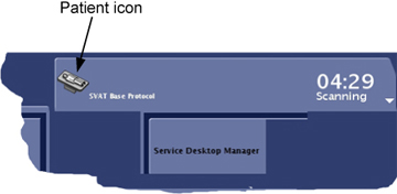
-
Slowly increase TG to 160 while adjusting the rotary attenuators (to prevent receiver over-range indicated by R1%>100 or R2% >100) until you achieve an R1% and R2% display on the manual prescan page of 84-94% with TG=160.
When using RFA to troubleshoot Dual Drive Quadrature Calibration issues, the transmit gain (TG) should be set to 160 for both channels because this is the nominal prescan value.
Do NOT change the attenuator settings for channel 2. The attenuator settings must be the same for both channels.
-
When done, click the Toolbelt icon to return to service window. Start the scan by selecting Proceed & auto-scan.
Figure 24. Message Box 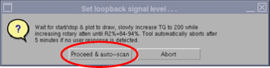
-
After the scan and analysis ends, view the results. Compare the results to the typical normal plots shown in Figure 25.
Real failures exceed the example plot values by 2 or more times. Minor differences are not failures. Select the popup choice to erase the displays. The plots are saved as JPG files under /usr/g/service/cclass/RFA/.
Figure 25. Sample RFA Plot Results 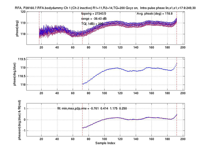
-
From the RFA Intra-Pulse Phase Linearity Plot Analysis 1, record the Topavg (magnitude) value and the Avg Phase deg (Phase) values for channel 1. You may need to resize to view values. Use Table 11 to record these values.
Note:If the plots are closed, they can be reopened. Go to directory /usr/g/service/cclass/RFA and open file with the suffix phafit.jpg.
For example: display P28160.7.RFA.bodydummy.2.phafit.jpg
Setup for Channel 2
-
On the exciter/ref clock module located in the PEN cabinet, set the RF Enb switch down (Disable).
-
To gather data from channel 2, set up the test configuration using the diagram and steps in the following illustration.
Figure 26. DTRSW Troubleshooting for Channel 2 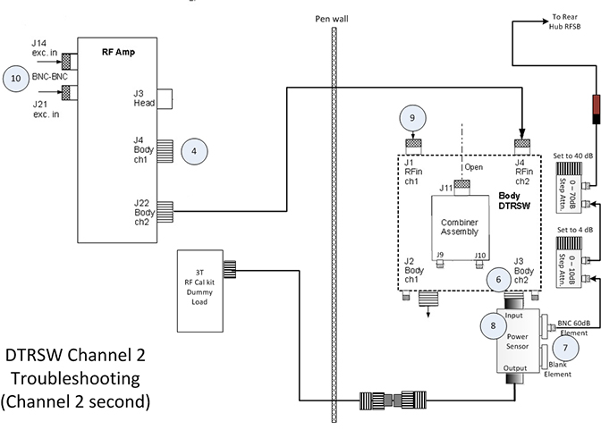
-
Reconnect Ch2 transmit cable at RF amplifier (J22).
-
Disconnect Ch1 transmit cable from the RF amplifier at J4. Connect the cable removed from J4 to the 3.0T 35 kW (50Ω) dummy load.
-
Remove the Ch2 RF output cable to body coil from the DTRSW at J3. Leave the cable disconnected.
-
Move the RF power sensor input (currently connected to J2) to J3.
-
Leave variable attenuators set in the same values as channel 1.
-
Remove the body receive cable from the preamp combiner at J11. Connect a DC block at the end of this cable and connect the other end of the DC block to the step attenuator.
-
Remove the Ch1 RF transmit cable at J1 of the DTRSW. Connect this end of the cable to the output side of the RF power sensor using the RF cable from the SST kit and several RF connectors from the RF power measurement kit.
- Disconnect J14 at the input of the RF amp.
-
On the exciter/ref clock module, set the RF Enb switch to up (Enable).
-
Repeat the steps in Data Analysis, changing the following on the RFA Analysis Tool (Figure 22):
-
Set Loopback Mode to Body Dummy
-
Set RF Pulse Type to Ascending
-
Set Dual Drive Output to Ch2 output only looped back and Disable Ch1 exciter output
-
-
After the scan is complete, reconnect J14 at the RF amplifier.
-
From the RFA Intra-Pulse Phase Linearity Plot Analysis 1, record the Topavg (or magnitude) value and the Avg Phase deg (or Phase) values for channel 2. You may need to resize to view values. Use Table 11 to record these values.
Note:If the plots are closed, they can be reopened from the JPG files where they are stored. Go to directory /usr/g/service/cclass/RFA and open the file with the suffix phafit.jpg.
For example: display P28160.7.RFA.bodydummy.2.phafit.jpg.
Running RFA: Channel 2 First
Complete these steps if channel 2 is the hot channel (see Determining “Hot” channel). If channel 1 is the hot channel, refer instead to Running RFA: channel 1 First.
Setup for Channel 2
-
Before running RFA, zero out any residual values in the DD Quadrature tool as follows:
-
On the Common Service Desktop, select Calibration then select DD Quadrature Calibration.
-
Select Reset.
-
Select Defaults (0,0).
-
Exit the DD Quadrature tool.
-
-
Ensure that the system is idle, and remove all portable coils from the bore.
-
Place the body TLT sphere and loader on the table. If you are using a GEM (flat) table, use the foam holder to contain the phantom.
-
Landmark the phantom.
-
On the driver module in the PEN cabinet, set switch 2 (SW2) to TR DISABLE and SW3 to DD DISABLE.
Figure 27. Setting TR and DD Disable -
On the exciter/ref clock module located in the PEN cabinet, set the RF Enb switch down (Disable).
-
To gather data from channel 2, set up the test configuration using the diagram and steps in the following illustration.
Figure 28. DTRSW Troubleshooting to Channel 2 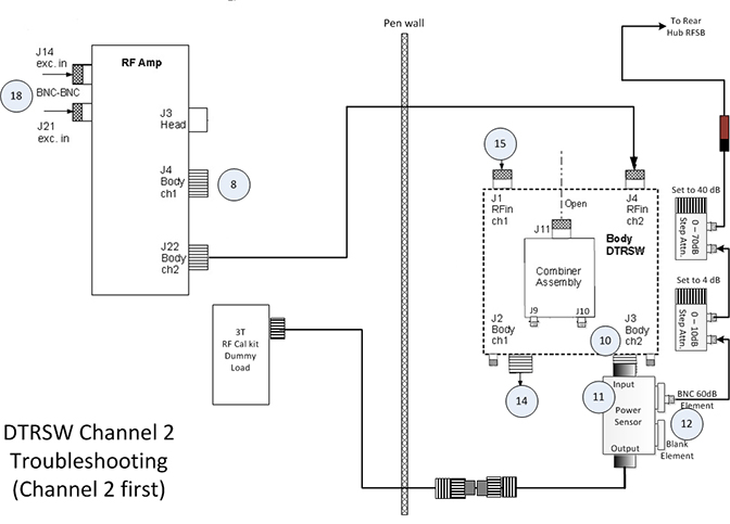
-
Disconnect Ch1 transmit cable from the RF amplifier at J4. Connect the cable removed from J4 to the 3.0T 35 kW (50Ω) dummy load.
-
Disconnect J7 and J8 at DTRSW. Leave cables disconnected.
-
Remove the Ch2 RF output cable to body coil from the DTRSW at J3. Leave the cable disconnected.
-
Place a 60 dB BNC element, labeled 2372868-22, into the Forward port of the 5010G RF power sensor. Install a metal element blank or any other sense element into the open port labeled Reflected on the power sensor. The Reflected port is not measured, so the type of element used to fill this port is not critical.
-
Connect the power sensor to J3 of the DTRSW.
-
Install two adjustable attenuators in series with the 60 dB element in the RF power sensor. Set up the attenuators. Set the 1 dB step attenuator to 4 dB, and the 10 dB step attenuator to 40 dB. Total additional attenuation provided by the step attenuators should be 44 dB.
-
Remove the body receive cable from the preamp combiner at J11. Connect a DC block at the end of this cable and connect the other end of the DC block to the step attenuator.
-
Disconnect the Ch1 RF transmit to body coil cable at J2 of the DTRSW. Leave the cable disconnected.
-
Disconnect the Ch1 RF transmit cable at J1 of the DTRSW. Connect this end of the cable to the output side of the RF power sensor using the RF cable from the SST kit and several RF connectors from the RF power measurement kit.
Table 10. Required Connectors and Cables Part Name Part Number Kit Name RF Connector, 7/16 (Female) -> N (Male) 2372868-16 3.0T RF Power Measurement Kit RF Connector, N-FEMALE -> HN (Male) 46-2211865P16 SST Kit RF Connector, HN (Female) -> 7/16 (Male) 2372868-17 3.0T RF Power Measurement Kit -
Disconnect the input cables to the preamp combiner at J9 and J10.
-
Disconnect J21 cable at the RF amplifier. Leave cable disconnected.
Data analysis
| Notice | |
|---|---|
- On the exciter/ref clock module located in the PEN cabinet, set the RF Enb switch to Enable (UP).
- Insert the service key into the PC.
- From the Common Service Desktop, select the Image Quality tab, and then select RFA.
- Set Loopback Mode to Body Dummy, RF Pulse Type to Ascending, Dual Drive Output to Ch1 output only looped back and Disable Ch2 exciter output.
- For channel 1, set Dual Drive Output to Ch1 output only looped back and Disable Ch2 exciter output.
- For channel 2, set Dual Drive Output to Ch2 output only looped back and Disable Ch1 exciter output.
- Click Start.Note:
SVAT errors usually indicate a setup problem such as landmark, 32-channel patient table connector not connected, TR or DD fault, etc. Check the error log.
- Check the loopback setup according to the pop-up request. Click Continue and then click Yes.
- After 60 seconds, a message box appears. Do NOT respond to the message box at this point. Click the Patient icon in the upper right of the display.
Figure 29. Patient Icon - Slowly increase TG to 160 while adjusting the rotary attenuators (to prevent receiver over-range indicated by R1%>100 or R2% >100) until you achieve an R1% and R2% display on the manual prescan page of 84-94% with TG=160.
When using RFA to troubleshoot Dual Drive Quadrature Calibration issues, the transmit gain (TG) should be set to 160 for both channels because this is the nominal prescan value.
Do NOT change the attenuator settings for channel 2. The attenuator settings must be the same for both channels.
- When done, click the Toolbelt icon to return to service window. Start the scan by selecting Proceed & auto-scan.
Figure 30. Message Box - After the scan and analysis ends, view the results. Compare the results to the sample normal plots shown in Figure 31.
Real failures exceed the example plot values by 2 or more times. Minor differences are not failures. Select the popup choice to erase the displays. The plots are saved as JPG files under /usr/g/service/cclass/RFA/.
Figure 31. Sample RFA Plot Results - From the RFA Intra-Pulse Phase Linearity Plot Analysis 1, record the Topavg (magnitude) value and the Avg Phase deg (Phase) values for channel 1. You may need to re-size to view values. Use Table 11 to record these values.Note:
If the plots are closed, they can be reopened. Go to directory /usr/g/service/cclass/RFA and open file with the suffix phafit.jpg.
For example: display P28160.7.RFA.bodydummy.2.phafit.jpg.
Setup for Channel 1
- On the exciter/ref clock module located in the PEN cabinet, set the RF Enb switch to down (Disable).
Figure 32. Exciter/Ref Clock Module - To gather data from the first channel, set up the test configuration using the diagram and steps below.
Figure 33. DTRSW Troubleshooting for Channel 1 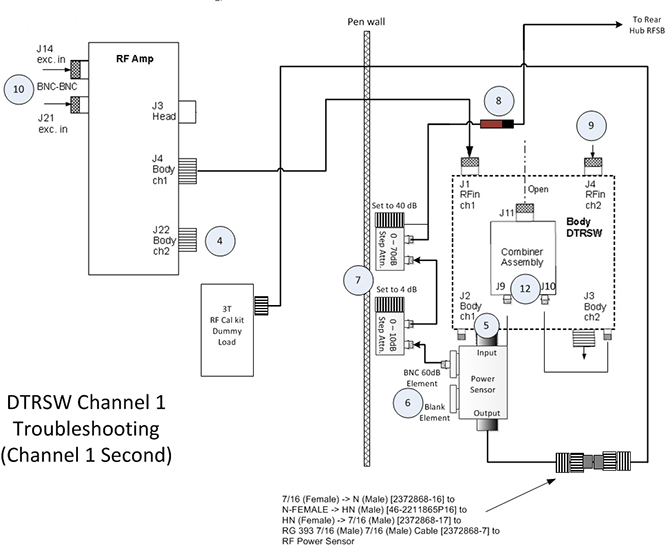
- Reconnect the Ch1 transmit cable at the RF amplifier (J4).
- Disconnect the Ch2 transmit cable from the RF amplifier at J22. Connect the cable from J22 to the 3.0T 35 kW (50Ω) dummy load.
- Remove the Ch1 RF output to body coil cable from the DTRSW at J2. Leave the cable disconnected.
- Move the RF power sensor input (currently connected to J3) to J2.
- Leave the variable attenuators set to the same values as channel 2.
- Remove the body receive cable from the preamp combiner at J11. Connect a DC block at the end of this cable and connect the other end of the DC block to the step attenuator.
- Remove the Ch2 RF transmit cable at J4 of the DTRSW. Connect this end to the output side of the RF power sensor using the RF cable from the SST kit and the two RF connectors from the RF power measurement kit.
- Disconnect J21 at the input of the RF amp.
- On the exciter/ref clock module, set the RF Enb switch to up (Enable).
- Repeat the steps in Data analysis, changing the following on the RFA Analysis Tool:
- Set Loopback Mode to bodydummy
- Set RF Pulse Type to Exp (Ascending)
- Set Dual Drive Output to Ch1 output only looped back and Disable Ch2 exciter output
Figure 34. RF Analysis Tool Menu - After the scan is complete, reconnect J21 at the RF Amplifier.
- From the RFA Intra-Pulse Phase Linearity Plot Analysis 1, record the Topavg (or magnitude) value and the Avg Phase deg (or Phase) values for channel 1. You may need to resize to view valves. Use Table 11 to record these values.Note:
If the plots are closed, they can be reopened from the JPG files where they are stored. Go to directory /usr/g/service/cclass/RFA and open the file with the suffix phafit.jpg.
For example: display P28160.7.RFA.bodydummy.2.phafit.jpg
Calculating dB difference
| Channel 1 | Channel 2 | |
| Topavg | ||
| Avg Phase deg |
- Calculate the dB difference using the following formula:

If the MagBal delta is greater than 0.5 dB (either positive or negative), there could be an issue with the system electronics. Check RF output. It is also recommended to run RFA at the output of the RF amplifier and the exciter to isolate cause of high MagBal.
However, if the MagBal delta is less than 0.5 dB, there could be an issue with the body coil tuning.
See Check Body Coil Tuning with Network Analyzer.
Note:If the plots are closed, they can be reopened from JPG files where they are stored. Go to directory /usr/g/service/cclass/RFA and open the file with the suffix phafit.jpg.
For example: display P28160.7.RFA.bodydummy.2.phafit.jpg
Note: When setting the variable attenuators for this test, do not change the settings. Channel 1 and channel 2 must be set at the same attenuation values for this test.If the phase difference between channel 1 and channel 2 is greater than 90 degrees, ±15 degrees (or 75 to 105 degrees), there could be an issue with the system electronics. It is recommended to run RFA at the output of the RF amplifier and the exciter to isolate the cause of the phase issue.
In the RFA results, channel 1 should lead channel 2. The phase of channel 1 should be +90 degrees relative to the phase of channel 2.
For example, if the phase for channel 1 is 110.0 degrees and the phase for channel 2 is -160.0 degrees, the actual phase difference is 90 degrees.Figure 35. Polar Chart 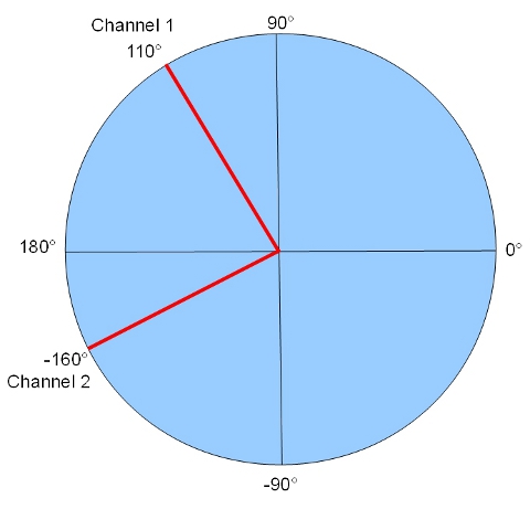
- If both the magnitude and phase results for the DTRSW output are acceptable, the problem is possibly in part of RF chain that is not included in RFA test loop, such as the RF body coil.
Finalization for RFA check
- Return the system to the normal operating configuration.
-
Run the calibration tool for the system (see Dual drive quadrature tool).
Check Body Coil Tuning with Network Analyzer
If the RF transmission from channel 1 and channel 2 is good, order a Network Analyzer (part #5336593-2). Follow the procedure for MR750w Body Coil Tuning to check and/or adjust the tuning on the body coil.
Non-electrical table option
About this task
Procedure
- List directory contents for QuadCal by typing ls -al QuadCal*.
Be aware that the site can have several files listed, depending on the number of GEM tables or the number of times QuadCal was run with different PA coils. Select the file with the latest date. This date represents the last time that QuadCal was executed for a GEM table or PA on the site’s system.
Only use the latest file with the “.dat” extension. Do not use files with the “.dat.LCV” or “.dat.old” file extensions.
Figure 36. Example: 
- Confirm that the FLAT0TABLE.dat file has passing calStatusH and calSatsusC value. Type more and paste the .dat file name that you copied from the C Shell.
If it does not have passing values, re-run quadrature calibration on the flat table to obtain passing values.
Figure 37. Example:  Note: When entering the name for the curved table, you must type in exact characters (case sensitive): QuadCal_N_0T0DV0M0CURVED0TABLE0xxxxxxxxxxx.dat.
Finalization
Procedure
- Complete SaveInfo.
- Remove the phantoms, pads, body loader, service filler panels (curved table), and curved adapter (flat table) from the cradle, and return them to the assigned storage locations.