Discovery MR750w and SIGNA™ Architect T 3.0T System Service Methods
5690002-2EN
Revision
4
Object ID: 00000018WIA30D0D030GYZ
Topic ID: id_12374209 Version: 1.7
Date: Jan 17, 2020 10:44:37 AM
Clock Splitter Replacement
Prerequisites
Table 1. Personnel requirements
Required persons
Preliminary requirements
Procedure
Finalization
1
Not Applicable
15 minutes
Not Applicable
Table 2. Tools and test equipment
Item
Quantity
Effectivity
Part number
Manufacturer
Standard Hand
Tools
1
-
-
Table 3. Replacement parts
Item
Quantity
Effectivity
Part number
Manufacturer
Clock Splitter
1
-
See FRU Manual
-
Table 4. Safety
DANGER
FATAL ELECTRIC SHOCK HAZARD!
Fatal voltages exist throughout the cabinet when energized.
TO PREVENT FATAL ELECTRIC SHOCK, DISCONNECT POWER FROM
THE PDU BEFORE continuing. PERFORM LOTO procedures PER GE REQUIREMENTS.
See the MR Service Safety Manual, PN 5452735.
Notice
Potential component damage
Electrostatic discharge (ESD) can cause permanent damage to electronic components.
Observe the following ESD precautions:
Work on a static-free mat.
Wear a static strap to make sure that any accumulated electrostatic charge is discharged from your body to the ground.
Create a common ground for the equipment being worked on by connecting the static-free mat, static strap, and peripheral units to that piece of equipment.
About this task
Overview
This procedure describes how to replace the clock splitter in
the PEN cabinet. The clock splitter exists in RRX receiver systems
with ICE or in systems upgraded to ICE.
Topic ID: id_SL16403056-1365986
Removing Clock Splitter
Procedure
Perform LOTO on the RF amplifier and the PEN cabinet. See the MR Service Safety Manual, PN 5452735.
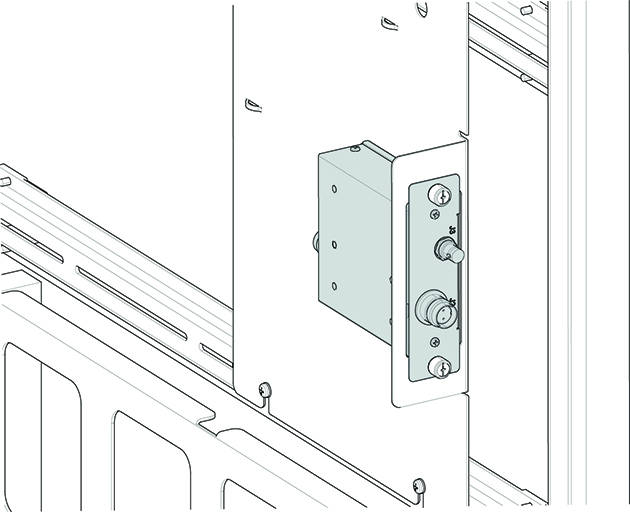
Loosen the thumbscrews from the clock splitter.
Figure 1. Clock Splitter
Disconnect the cables to the clock splitter. Note all the cable
locations for reconnection.
Remove the clock splitter from the bracket.
Topic ID: id_SL16403062-1365986
Installing Clock Splitter
Procedure
Install the new clock splitter in the bracket as shown in Figure 1.
Notice
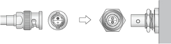
Clock cables on the splitter are Twin BNC connector cables. Align pins and keys before connection after replacement.
Connect the clock splitter cables as marked.
Tighten the thumbscrews to secure the clock splitter to the
bracket.
Notice
After LOTO is removed and power is reapplied to PEN cabinet, allow 30 minutes for the exciter to reach operating temperature and stabilize before calibrating or scanning.
Remove LOTO. See the MR Service Safety Manual, PN 5452735.
Topic ID: id_15194395
Finalization
Finalization
Perform a quick head and body scan to ensure the system is functioning
properly.