
- SIGNA MR355 / SIGNA MR360
- Service Manual
- 5856356-3EN Revision 5.0
- Basic Service Documentation. Copyright General Electric Company.
- 00000018WIA3019EF20GYZ
- id_131070361.3
- Jul 5, 2019 10:25:10 PM
TABLE CONTROL BOARD CABLES
Prerequisites
| Required persons | Preliminary requirements | Procedure | Finalization |
|---|---|---|---|
| 1 | 0 minutes | 120 minutes | 0 minutes |
| Item | Quantity | Effectivity | Part number | Manufacturer |
|---|---|---|---|---|
| Spanners (1/2,3/4,3/8,7/16,5/16,32) | One for each size | - | - | - |
| Circlip inserter (A-150,A170) | One for each size | - | - | - |
| Hex. Socket (9/16,3/4,3/8) | One for each size | - | - | - |
| Scale (15cms & 30 cms) | One for each size | - | - | - |
| Ball driver (5/32,5/64,3/32,1/8,7/64,9/16) | One for each size | - | - | - |
| Allen key (5/32,5/64,3/32,1/8,7/64,9/16) | One for each size | - | - | - |
| Flat nose plier | - | - | - | - |
| Cutter | - | - | - | - |
| Copper hammer | - | - | - | - |
| Screw driver (8mm, 4mm) | One for each size | - | - | - |
| Knife | - | - | - | - |
| Soft mallet | - | - | - | - |
| Torque wrench (40-120 kg-cm,10 –50 lb-ft) | - | - | - | - |
| Item | Quantity | Effectivity | Part number | Manufacturer |
|---|---|---|---|---|
| Locktite / Primer (242, 569, 680, 415, 770) | One for each size | - | - | - |
| IPA | - | - | - | - |
| White Marker | - | - | - | - |
| Grease Mobil HSC 32 | - | - | - | - |
| Cotton waste White (High grade) | - | - | - | - |
| ||||||||
Procedure
- Remove the spiral tube wounded to all Assemblies.
Figure 1. Remove the spiral tube 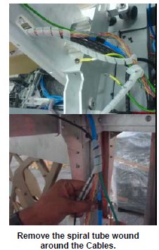
- Disconnect the Cables from the Control Box extension cable.
Figure 2. Disconnect the Cables 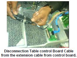
- Remove the cables connected to the Up sensor Limit switch.
Figure 3. Remove the cables 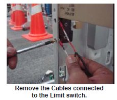
- Remove the Tabletop RH panel in the tabletop assembly.
Figure 4. Remove the Tabletop RH panel 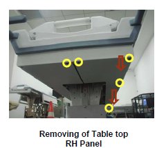
- Remove the cables connected to the Limit switch of the home
sensor.
Figure 5. Remove the cables 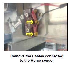
- Rout the lengthier end of the cable in the tabletop.
Figure 6. Rout 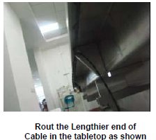
- Connect the cable lengthier end to the Limit switch of the home
sensor.
Figure 7. Connect the cable 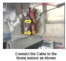
- Fix the Tabletop RH panel in the tabletop assembly.
Figure 8. Fix the Tabletop RH panel 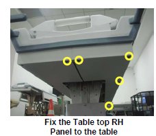
- Connect the Shorter length end of the cable to the Limit switch.
Figure 9. Connect the Shorter length end of the cable 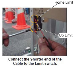
- Rout the cables in the table and wind the spiral tube around
all Assemblies.
Figure 10. Rout the cables 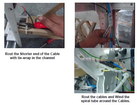
Finalization
- Turn the system Power ON. Refer to Lockout / Tagout for System Cabinet PDU Main Breaker.
- Level the Table and perform Height Adjustment. Refer to LEVELING FIXED TABLE and TOP HEIGHT ADJUSTMENT.
- Perform Fixed Table Functional Check. Refer to TABLE CHECKS AFTER INSTALLATION .