
- SIGNA MR355 / SIGNA MR360
- Service Manual
- 5856356-3EN Revision 5.0
- Basic Service Documentation. Copyright General Electric Company.
- 00000018WIA308E6360GYZ
- id_20305351.2
- Feb 6, 2021 10:17:04 PM
New 25KVA PDU theory
Important safety instructions
SAVE THESE INSTRUCTIONS – This manual contains important instruction for 1.5T new 25kVA Power Distribution Unit (PDU) that must be followed during installation, operation, and maintenance.
| DANGER | |
|---|---|
| Notice | |
|---|---|
Introduction
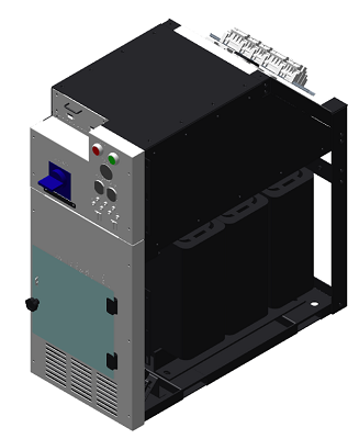
The Power Distribution Unit (PDU) distributes power to various components of a General Electric Medical Systems MRI system. Three phase input voltage is selectable among six levels: 200/208/380/400/415/480 VAC. Rated frequency is 50/60 Hz. Power rating is 25 KVA continuous, 30 KVA instantaneous. The PDU mounts in a System Cabinet Rack.
Scope
This manual describes procedures for installation, basic operation of the Power Distribution Unit, simple diagnosis/isolation, and schematics of the PDU. Replacement of FRU parts are described in 'Replacement' tab CD-ROM manual.
Specifications
Specifications subject to revision without notice
- Electrical specifications:
- Power Rating: 25 KVA Continuous; 30 KVA Instantaneous
- Input Voltage: 200/208/380/400/415/480 VAC Delta, User SelectableNote:
Factory wired for 480VAC Delta
- Output Voltage: 380/208/120 VAC WYE
- Overload Protection: Main Input Circuit Breaker with adjustable trip settings; Output distribution circuit breakers
- Night Mode: Save Power when System is standby mode
Installation - Input Voltage Selection
Before connecting the input power cables, determine the nominal value of the input voltage. The PDU allows for nominal input voltages of 200, 208, 380, 400, 415, or 480 VAC (three phase). Input voltage selection is accomplished as follows:
- On the Main Disconnect Panel (MDP), turn off the PDU circuit breaker, lock and tag appropriately.
- Using a voltmeter or other voltage indicating device at the Primary Test Jack, check to be sure that no voltage is being applied to the input of the PDU.
- Remove the front cover of System Cabinet and the lower plate of PDU.
Figure 2. PDU lower plate 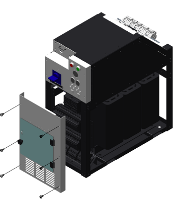
- Each of the three phases, be sure the wire is connected to the proper terminal for the actual input voltage at the site.
Figure 3. Example of 480VAC input connection mode 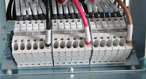
- The overload and short circuit trip settings for the Main Input Circuit Breaker must be set to the correct values corresponding to the input voltage.
-
Remove the upper plate of front panel by release 5 screws. Then could access to the dip switches controlling the circuit breaker operation.
Figure 4. PDU upper plate 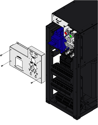
-
Set the dip SW to the correct value corresponding to the input voltage.
Figure 5. Circuit breaker DIP switch settings 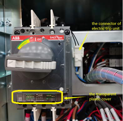
Primary voltage(V) L I1=In x (0.4+Σ) t1 S/I I3 I3=In x Σ 0.04 0.08 0.16 0.32 1 1.5 2 5.5 t2 200 92 X X X 36s I 10 X X X X 0.2s 208 88 X X 36s I 10 X X X X 0.2s 380 52 X X 36s I 6.5 X X 0.2s 400 48 X 36s I 6.5 X X 0.2s 415 44 X 36s I 6.5 X X 0.2s 480 40 36s I 5.5 X 0.2s
-
| Notice | |
|---|---|
| Input Voltage | 200V | 208 V | 380 to 480 V |
| Maximum input current | 80A | 76A | 40A |