- SIGNA MR355 / SIGNA MR360
- Service Manual
- 5856356-3EN Revision 5.0
- Basic Service Documentation. Copyright General Electric Company.
- 00000018WIA30414F20GYZ
- id_131068961.1
- Jul 5, 2019 10:46:04 PM
Cabinet Monitor Design Specification
Overview
This document describes hardware design specification of the Cabinet Monitor, which is used in SV 1.5T MRI system.
Purpose
The Cabinet Monitor shall monitor the leakage from the cooling system, the temperature in the cabinet, water tank level and flow of the cooling system. The Cabinet Monitor shall drive relay driver, Emergency Stop, if necessary. The Cabinet Monitor shall communication with SCP via CAN.
Function Overview
Power Supply
-
Main Power Supply Switch ・・・Cabinet Monitor Main Power
-
Fuse ・・・M, 3A/250V, replaceable fuse folder
Interface
Cabinet Monitor Board has the following interfaces.
-
Leakage Sensor (2, 3)
-
Leakage ・・・leakage signal input
-
sensor fault ・・・sensor fault signal input
-
-
Temperature Sensor (1, 2)
-
OUT1 ・・・temperature sensor out1 input
-
OUT2 ・・・temperature sensor out2 input
-
-
Water Level Sensor ・・・Water Tank Level signal input
-
BRM PUMP Status ・・・BRM Pump Status signal input
-
Cabinet PUMP Status ・・・Cabinet Pump Status signal input
-
Standby Mode ・・・Standby Mode signal(RS422) input
-
CAN ・・・Board Control interface
-
E-off ・・・Relay control signal output (RelayDriver2)
-
Standby ・・・Relay control signal output (RelayDriver5)
-
Magnet Monitor Output ・・・Relay point output(Relay6)
Configuration
This main configuration of the Cabinet Monitor should consist of three power supplies (24V, 5V and isolated 24V for CAN), three leakage detectors, 6 relay drivers and 14 LEDs. The Cabinet Monitor can monitor leakage and sensor fault by each leakage detector, over temperature by two Temps Sensor (GEHC P/N 2184426), flow SW and tank level SW of Cooling Unit. The Cabinet Monitor can drive the 6 relay drivers. It has 14 Input ports for sensors. The Cabinet Monitor has a CAN communication port and supply 24V DC power, which can communicate with SCP by CAN.
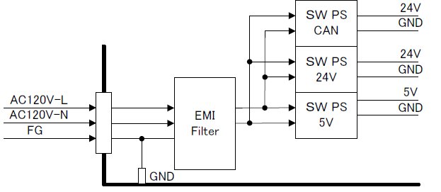
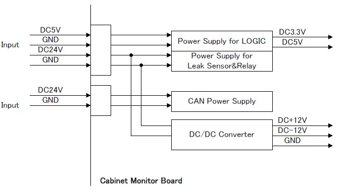
The assemblies that make up the cabinet monitor are as follows.EMI filter: filter the input 120VAC power supply. AC-DC output power supplies( 120VAC to 24VDC, 120VAC to CAN 24VDC, 120VAC to 5VDC, and 5VDC to 3.3VDC) The sub-assemblies supply power for the whole cabinet monitor. Cabinet monitor control board: process the I/O signals and drive relay dirvers CAN Communication Core Board assembly: the channel of CAN communication with SCP Leak sensor Amplifier board (3 pieces): detect the leak sensors status, leakage and disconnection.
In this illustration, the Leakage Sensor1, Primary Trans, DCERD2 PS and LK1 LED SF1 LED are not used in SV system.
Electrical Specification
Power Voltage
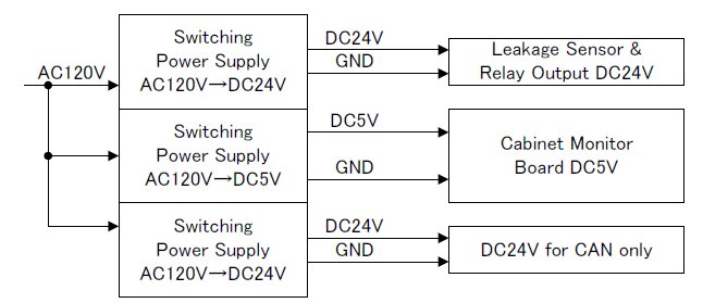
The AC120V shall be provided from the Cabinet. The DC24V or DC5V switching power supply in the Cabinet Monitor shall provide DC24V or DC5V to the board, sensors, relays and CAN power. CAN power supply should be isolated from another power supply.
LED indicator
This table shows the LED indicators on the front panel.
| Name | LED Color | Description |
| LK1 | Red | Leakage Sensor1 Leakage (not used) |
| SF1 | Yellow | Leakage Sensor1 Sensor fault (not used) |
| LK2 | Red | Leakage Sensor2 Leakage |
| SF2 | Yellow | Leakage Sensor2 Sensor fault |
| Lk3 | Red | Leakage Sensor3 Leakage |
| SF3 | Yellow | Leakage Sensor3 Sensor fault |
| L45 | Red | Temperature Sensor1 |
| L40 | Yellow | Temperature Sensor1 |
| R45 | Red | Temperature Sensor2 |
| R40 | Yellow | Temperature Sensor2 |
| DCERD | Red | DCERD Alarm (not used) |
| BRM Pump | Red | BRM Pump Alarm |
| Tank | Red | Water Level Sensor |
| Cabinet PUMP | Red | Cabinet PUMP Status |
Connection with Interface
This section explains the interface connection of the Cabinet Monitor.
Leakage Sensor1(Mini Mete-N-Lok, 3pin) (not used)
| Pin No. | Signal Name | Function | Signal Direction |
| 1 | Vtest- | Voltage negative of the leak sensor strip terminal | 0 ~ 3.3V DC |
| 2 | NC | NC | NC |
| 3 | Vtest+ | Voltage positive of the leak sensor strip terminal | 0 ~ 3.3V DC |
Leakage Sensor2(Mini Mete-N-Lok, 3pin)
| Pin No. | Signal Name | Function | Signal Direction |
| 1 | Vtest- | Voltage negative of the leak sensor strip terminal | 0 ~ 3.3V DC |
| 2 | NC | NC | NC |
| 3 | Vtest+ | Voltage positive of the leak sensor strip terminal | 0 ~ 3.3V DC |
Leakage Sensor3(Mini Mete-N-Lok, 3pin)
| Pin No. | Signal Name | Function | Signal Direction |
| 1 | Vtest- | Voltage negative of the leak sensor strip terminal | 0 ~ 3.3V DC |
| 2 | NC | NC | NC |
| 3 | Vtest+ | Voltage positive of the leak sensor strip terminal | 0 ~ 3.3V DC |
Temperate Sensor1, Left Cabinet
| Pin No. | Signal Name | Function | Signal Direction |
| 1 | N.C. | - | - |
| 2 | VCC | DC5V | - |
| 3 | N.C. | - | - |
| 4 | VCC | DC5V | - |
| 5 | N.C. | - | - |
| 6 | OUT1 | High : more than 40℃ | Input TTL signal |
| 7 | GND | GND | - |
| 8 | OUT2 | High : more than 45℃ | Input TTL signal |
| 9 | GND | GND | - |
| 10 | - | - | - |
Temperate Sensor2, Right Cabinet
| Pin No. | Signal Name | Function | Signal Direction |
| 1 | N.C. | - | - |
| 2 | VCC | DC5V | - |
| 3 | N.C. | - | - |
| 4 | VCC | DC5V | - |
| 5 | N.C. | - | - |
| 6 | OUT1 | High : more than 40±3℃ | Input |
| 7 | GND | GND | - |
| 8 | OUT2 | High : more than 45±3℃ | Input |
| 9 | GND | GND | - |
| 10 | N.C. | - | - |
BRM PUMP status(Mini Mete-N-Lok, 2pin)
| Pin No. | Signal Name | Function | Signal Direction |
| 1 | BRM Pump Alarm signal | BRM Pump Alarm input signal | Input short/open signal (Normal open) |
| 2 | GND | GND | - |
Water Level Sensor(Mini Mete-N-Lok, 3pin)
| Pin No. | Signal Name | Function | Specification |
| 1 | - | - | - |
| 2 | Water Level Signal | Water Level input signal | Input short/open signal (Normal Open) |
| 3 | GND | GND | - |
Cabinet PUMP Status(Mini Mete-N-Lok, 2pin)
| Pin No. | Signal Name | Function | Signal Direction |
| 1 | Cabinet PUMP Alarm signal | Cabinet Pump Alarm input signal | Input short/open signal (Normal open) |
| 2 | GND | GND | - |
Standby Mode(D-sub 9pin, Receipt)
| Pin No. | Signal Name | Function | Signal Direction |
| 1 | N.C. | Connection with CCC Board CAN connector 1pin | - |
| 2 | CAN_LOW | CAN_LOW line | Input/Output |
| 3 | GND | CAN GND | - |
| 4 | N.C. | Connection with CCC Board CAN connector 7pin | - |
| 5 | Connection with CAN2 connector 5pin | - | |
| 6 | GND | CAN GND | - |
| 7 | CAN_HIGH | CAN_HIGH line | Input/Output |
| 8 | N.C. | Connection with CCC Board CAN connector 6pin | - |
| 9 | DC24V | DC24V | - |
CAN1(D-sub 9pin, Receipt)
| Pin No. | Signal Name | Function | Signal Direction |
| 1 | N.C. | Connection with CCC Board CAN connector 1pin | - |
| 2 | CAN_LOW | CAN_LOW line | Input/Output |
| 3 | GND | CAN GND | - |
| 4 | N.C. | Connection with CCC Board CAN connector 7pin | - |
| 5 | N.C. | Connection with CAN2 connector 5pin | - |
| 6 | GND | CAN GND | - |
| 7 | CAN_HIGH | CAN_HIGH line | Input/Output |
| 8 | N.C. | Connection with CCC Board CAN connector 6pin | - |
| 9 | DC24V | DC24V | - |
CAN2(D-sub 9pin, Plug)
| Pin No. | Signal Name | Function | Signal Direction |
| 1 | N.C. | Connection with CCC Board CAN connector 1pin | - |
| 2 | CAN_LOW | CAN_LOW line | Input/Output |
| 3 | GND | CAN GND | - |
| 4 | N.C. | Connection with CCC Board CAN connector 7pin | - |
| 5 | N.C. | Connection with CAN2 connector 5pin | - |
| 6 | GND | CAN GND | - |
| 7 | CAN_HIGH | CAN_HIGH line | Input/Output |
| 8 | N.C. | Connection with CCC Board CAN connector 6pin | - |
| 9 | DC24V | DC24V | - |
Relay Drive (D-sub 15pin, Receipt)
| Pin No. | Signal Name | Function | Signal Direction |
| 1 | Driver1 (+) | Relay1 control signal(+) | Output |
| 2 | Driver1 (-) | Relay1 control signal (-) | Output |
| 3 | Driver2 (+) | Relay2 control signal (+) | Output |
| 4 | Driver2 (-) | Relay2 control signal (-) | Output |
| 5 | Driver3 (+) | Relay3 control signal (+) | Output |
| 6 | Driver3 (-) | Relay3 control signal (-) | Output |
| 7 | Driver4 (+) | Relay4 control signal (+) | Output |
| 8 | Driver4 (-) | Relay4 control signal (-) | Output |
| 9 | Driver5 (+) | Relay5 control signal (+) | Output |
| 10 | Driver5 (-) | Relay5 control signal (-) | Output |
| 11 | N.C. | - | - |
| 12 | N.C. | - | - |
| 13 | N.C. | - | - |
| 14 | N.C. | - | - |
| 15 | N.C. | - | - |
Magnet Monitor Out(Mini Mete-N-Lok, 2pin)
| Pin No. | Signal Name | Function | Signal Direction |
| 1 | Relay point 1 | Relay Signal | Output |
| 2 | Relay point 2 | Relay Signal | Output |
Board Electrical Specification
Power Voltage
The Switching Power Supply(VS10C-5) provide DC5V to the board and the Cabinet Monitor Board produces DC3.3V. The power voltage(DC5V,DC24V,CAN DC24V) shall be isolated and then provide to the each device.
-
LOGIC Power ・・・・・・・・・・・DC5V,DC3.3V,DC±12V
-
CAN Power ・・・・・・・・・・・DC24V
-
Leakage Sensor/Relay Power ・・・・DC24V
* DC±12V shall be isolated electrically
Connection
In this section, the following shows the connection with Cabinet Monitor Board.
Power Connector(J1)
| Pin No. | Signal Name | Function | Signal Direction |
| 1 | 5V | DC5V | - |
| 2 | GND | GND(5V/3.3V) | - |
| 3 | N.C. | - | - |
| 4 | 24V | DC24V | - |
| 5 | GND | GND(24V) | - |
CAN Power Connector(J2)
| Pin No. | Signal Name | Function | Signal Direction |
| 1 | GND | GND(CAN-24V) | - |
| 2 | N.C. | - | - |
| 3 | 24V | DC24V | - |
CCC Board Connector(CN1)
| Pin No. | Signal Name | Function | Signal Direction |
| 1 | 3.3V | DC3.3V | - |
| 2 | L-GND | Logic-GND | - |
| 3 | N.C. | - | - |
| 4 | L-GND | Logic-GND | - |
| 5 | L-GND | Logic-GND | - |
| 6 | SPICLK | Not used. | - |
| 7 | L-GND | Logic-GND | - |
| 8 | L-GND | Logic-GND | - |
| 9 | N.C. | - | - |
| 10 | L-GND | Logic-GND | - |
| 11 | L-GND | Logic-GND | - |
| 12 | SPISOMI | Not used. | - |
| 13 | IOPB3 | Input MUX Control bit3 | Input |
| 14 | L-GND | Logic-GND | - |
| 15 | L-GND | Logic-GND | - |
| 16 | SPISIMO | Not used. | - |
| 17 | IOPB2 | Input MUX Control bit2 | Input |
| 18 | L-GND | Logic-GND | - |
| 19 | 5V | DC 5V | - |
| 20 | 3.3V | DC 3.3V | - |
| 21 | IOPE5 | Not used. | - |
| 22 | L-GND | Logic-GND | - |
| 23 | L-GND | Logic-GND | - |
| 24 | SPISTE or SPI_CS1 | Not used. | - |
| 25 | IOPB1 | Input MUX Control bit1 | Input |
| 26 | L-GND | Logic-GND | - |
| 27 | L-GND | Logic-GND | - |
| 28 | L-GND | Logic-GND | - |
| 29 | IOPB0 | Input MUX output | Output |
| 30 | L-GND | Logic-GND | - |
| 31 | L-GND | Logic-GND | - |
| 32 | 5V | DC 5V | - |
| 33 | IOPA7 | Output MUX Control bit4 | Input |
| 34 | L-GND | Logic-GND | - |
| 35 | L-GND | Logic-GND | - |
| 36 | 3.3V | DC 3.3V | - |
| 37 | IOPE4 | Node ID bit4 | Output |
| 38 | L-GND | Logic-GND | - |
| 39 | L-GND | Logic-GND | - |
| 40 | SCIRXD | DEBUG PORT | Output |
| 41 | IOPA6 | Output MUX Control bit3 | Input |
| 42 | L-GND | Logic-GND | - |
| 43 | L-GND | Logic-GND | - |
| 44 | SCITXD | DEBUG PORT | Input |
| 45 | IOPE3 | Node ID bit3 | Output |
| 46 | L-GND | Logic-GND | - |
| 47 | L-GND | Logic-GND | - |
| 48 | XINT1 | Not used. | - |
| 49 | IOPE2 | Node ID bit2 | Output |
| 50 | L-GND | Logic-GND | - |
| 51 | L-GND | Logic-GND | - |
| 52 | XINT2 | Not used. | - |
| 53 | IOPE1 | Node ID bit1 | Output |
| 54 | L-GND | Logic-GND | - |
| 55 | L-GND | Logic-GND | - |
| 56 | IOPB5 | Input MUX Control bit5 | Input |
| 57 | CCC_STATUS_LED | Not used. | - |
| 58 | L-GND | Logic-GND | - |
| 59 | 5V | DC 5V | - |
| 60 | IOPB4 | Input MUX Control bit4 | Input |
| 61 | IOPE0 | Node ID bit0 | Output |
| 62 | L-GND | Logic-GND | - |
| 63 | L-GND | Logic-GND | - |
| 64 | IOPB6 | Not used. | - |
| 65 | IOPA5 | Output MUX Control bit2 | Input |
| 66 | L-GND | Logic-GND | - |
| 67 | L-GND | Logic-GND | - |
| 68 | IOPA3 | Output MUX output | Input |
| 69 | IOPA4 | Output MUX Control bit1 | Input |
| 70 | LOOPBACK | Not used. | - |
| 71 | L-GND | Logic-GND | - |
| 72 | LOOPBACK | Not used. | - |
| 73 | CCC_ERROR_LED | Not used. | - |
| 74 | L-GND | Logic-GND | - |
| 75 | L-GND | Logic-GND | - |
| 76 | RESET | Not used. | - |
| 77 | 5V | DC 5V | - |
| 78 | L-GND | Logic-GND | - |
| 79 | L-GND | Logic-GND | - |
| 80 | IOPC1 | Not used. | - |
| 81 | 5V | DC 5V | - |
| 82 | 3.3V | DC 3.3V | - |
| 83 | A-GND | Analog-GND | - |
| 84 | A-GND | Analog-GND | - |
| 85 | A-GND | Analog-GND | - |
| 86 | ADCIN15 | Not used. | - |
| 87 | 3.3V | DC 3.3V | - |
| 88 | A-GND | Analog-GND | - |
| 89 | A-GND | Analog-GND | Output |
| 90 | ADCIN07 | Not used. | - |
| 91 | ADCUN06 | Not used. | - |
| 92 | A-GND | Analog-GND | - |
| 93 | A-GND | Analog-GND | - |
| 94 | ADCIN14 | Not used. | - |
| 95 | ADCIN05 | Not used. | - |
| 96 | A-GND | Analog-GND | - |
| 97 | A-GND | Analog-GND | - |
| 98 | ADCIN04 | Not used. | - |
| 99 | ADCIN13 | Not used. | - |
| 100 | A-GND | Analog-GND | - |
| 101 | A-GND | Analog-GND | - |
| 102 | ADCIN03 | CAN DC 24V monitor | Output |
| 103 | ADCIN12 | Not used. | - |
| 104 | A-GND | Analog-GND | - |
| 105 | A-GND | Analog-GND | - |
| 106 | ADCIN02 | DC 3.3V monitor | Output |
| 107 | ADCIN11 | Not used. | - |
| 108 | A-GND | Analog-GND | - |
| 109 | A-GND | Analog-GND | - |
| 110 | ADCIN10 | Not used. | - |
| 111 | ADCIN01 | DC 5V monitor | Output |
| 112 | A-GND | Analog-GND | - |
| 113 | A-GND | Analog-GND | - |
| 114 | ADCIN09 | Not used. | - |
| 115 | ADCIN00 | DC 24V monitor | Output |
| 116 | A-GND | Analog-GND | - |
| 117 | A-GND | Analog-GND | - |
| 118 | L-GND | Logic-GND | - |
| 119 | ADCIN08 | Not used. | - |
| 120 | 3.3V | DC 3.3V | - |
Leakage Sensor Connector(J3)
| Pin No. | Signal Name | Function | Signal Direction |
| 1 | OUT+ | Leakage input(Sensor1) | Input |
| 2 | BURN OUT+ | Sensor fault input(Sensor1) | Input |
| 3 | COM- | Common GND | Output |
| 4 | N.C. | - | |
| 5 | 24V | Not used | - |
| 6 | GND | Not used | - |
| 7 | N.C. | - | |
| 8 | OUT+ | Leakage input(Sensor2) | Input |
| 9 | BURN OUT+ | Sensor fault input(Sensor2) | Input |
| 10 | COM- | Common GND | Output |
| 11 | N.C. | - | |
| 12 | 24V | Not used | - |
| 13 | GND | Not used | - |
| 14 | N.C. | - | |
| 15 | OUT+ | Leakage input(Sensor3) | Input |
| 16 | BURN OUT+ | Sensor fault input(Sensor3) | Input |
| 17 | COM- | Common GND | Output |
| 18 | N.C. | - | |
| 19 | 24V | Not used | - |
| 20 | GND | Not used | - |
Temperate Sensor1(Left Cabinet) Connector(J4)
| Pin No. | Signal Name | Function | Signal Direction |
| 1 | N.C. | - | - |
| 2 | VCC | DC5V | - |
| 3 | N.C. | - | - |
| 4 | VCC | DC5V | - |
| 5 | N.C. | - | - |
| 6 | OUT1 | Signal becomes high, if temperature becomes more than 40±3℃ | Input |
| 7 | GND | GND(5V/3.3V) | - |
| 8 | OUT2 | Signal becomes high, if temperature becomes more than 45±3℃ | Input |
| 9 | GND | GND(5V/3.3V) | - |
| 10 | N.C. | - | - |
Temperate Sensor2(Right Cabinet) Connector(J5)
| Pin No. | Signal Name | Function | Signal Direction |
| 1 | N.C. | - | - |
| 2 | VCC | DC5V | - |
| 3 | N.C. | - | - |
| 4 | VCC | DC5V | - |
| 5 | N.C. | - | - |
| 6 | OUT1 | Signal becomes high, if temperature becomes more than 40±3℃ | Input |
| 7 | GND | GND(5V/3.3V) | - |
| 8 | OUT2 | Signal becomes high, if temperature becomes more than 45±3℃ | Input |
| 9 | GND | GND(5V/3.3V) | - |
| 10 | N.C. | - | - |
Alarm Connector(J6)
| Pin No. | Signal Name | Function | Signal Direction |
| 1(not used) | DCERD signal (not used) | DCERD Input signal (not used) | Input (not used) |
| 2 | GND | GND(5V/3.3V) | - |
| 3 | N.C. | - | - |
| 4 | BRM Pump signal | BRM Pump Input signal | Input |
| 5 | GND | GND(5V/3.3V) | - |
| 6 | N.C. | - | - |
| 7 | Cabinet PUMP signal | Cabinet PUMP Input signal | Input |
| 8 | GND | GND(5V/3.3V) | - |
Water Level Connector(J7)
| Pin No. | Signal Name | Function | Signal Direction |
| 1 | N.C. | N.C. | - |
| 2 | Water Level signal | Water Level Input signal | Input open/short signal(Normal open) |
| 3 | GND | GND(5V/3.3V) | - |
LED Connector1(J8)
| Pin No. | Signal Name | Function | Signal Direction |
| 1 | leakage1_Anode (not used) | Leakage Sensor1 leakage LED Anode Signal | Output |
| 2 | leakage1_Cathode (not used) | Leakage Sensor1 leakage LED Cathode Signal | Output |
| 3 | burnout1_Anode (not used) | Leakage Sensor1 sensor fault LED Anode Signal | Output |
| 4 | burnout1_Cathode (not used) | Leakage Sensor1 sensor fault LED Cathode Signal | Output |
| 5 | leakage2_Anode | Leakage Sensor2 leakage LED Anode Signal | Output |
| 6 | leakage2_Cathode | Leakage Sensor2 leakage LED Cathode Signal | Output |
| 7 | burnout2_Anode | Leakage Sensor2 sensor fault LED Anode Signal | Output |
| 8 | burnout2_Cathode | Leakage Sensor2 sensor fault LED Cathode Signal | Output |
| 9 | leakage3_Anode | Leakage Sensor3 leakage LED Anode Signal | Output |
| 10 | leakage3_Cathode | Leakage Sensor3 leakage LED Cathode Signal | Output |
| 11 | burnout3_Anode | Leakage Sensor3 sensor fault LED Anode Signal | Output |
| 12 | burnout3_Cathode | Leakage Sensor3 sensor fault LED Cathode Signal | Output |
| 13 | Temp1_out2_Anode | Temp Sensor1 out2 LED Anode Signal | Output |
| 14 | Temp1_out2_Cathode | Temp Sensor1 out2 LED Cathode Signal | Output |
LED Connector2(J9)
| Pin No. | Signal Name | Function | Signal Direction |
| 1 | Temp1_out1_Anode | Temp Sensor1 out1 LED Anode Signal | Output |
| 2 | Temp1_out1_Cathode | Temp Sensor1 out1 LED Cathode Signal | Output |
| 3 | Temp2_out2_Anode | Temp Sensor2 out2 LED Anode Signal | Output |
| 4 | Temp2_out2_Cathode | Temp Sensor2 out2 LED Cathode Signal | Output |
| 5 | Temp2_out1_Anode | Temp Sensor2 out1 LED Anode Signal | Output |
| 6 | Temp2_out1_Cathode | Temp Sensor2 out1 LED Cathode Signal | Output |
| 7 | DCERD_Anode (not used) | DCERD LED Anode Signal | Output |
| 8 | DCERD_Cathode (not used) | DCERD LED Cathode Signal | Output |
| 9 | BRM cooling Pump_Anode | BRM cooling Pump LED Anode Signal | Output |
| 10 | BRM cooling Pump_Cathode | BRM cooling Pump LED Cathode Signal | Output |
| 11 | WaterLevel_Anode | WaterLevel LED Anode Signal | Output |
| 12 | WaterLevel Cathode | WaterLevel LED Cathode Signal | Output |
| 13 | Cabinet cooling Pump_Anode | Cabinet cooling Pump Anode Signal | Output |
| 14 | Cabinet cooling Pump_Cathode | Cabinet cooling Pump Cathode Signal | Output |
Relay Drive Connector(J14)
| Pin No. | Signal Name | Function | Signal Direction |
| 1 | Driver1 (+) | Relay1 control signal(+) | Output |
| 2 | Driver1 (-) | Relay1 control signal (-) | Output |
| 3 | Driver2 (+) | Relay2 control signal (+) | Output |
| 4 | Driver2 (-) | Relay2 control signal (-) | Output |
| 5 | Driver3 (+) | Relay3 control signal (+) | Output |
| 6 | Driver3 (-) | Relay3 control signal (-) | Output |
| 7 | Driver4 (+) | Relay4 control signal (+) | Output |
| 8 | Driver4 (-) | Relay4 control signal (-) | Output |
| 9 | Driver5 (+) | Relay5 control signal (+) | Output |
| 10 | Driver5 (-) | Relay5 control signal (-) | Output |
| 11 | N.C. | - | - |
| 12 | N.C. | - | - |
| 13 | N.C. | - | - |
| 14 | N.C. | - | - |
| 15 | N.C. | - | - |
Magnet Monitor Out Connector(J13)
| Pin No. | Signal Name | Function | Signal Direction |
| 1 | Relay Point1 | Relay Signal | Output |
| 2 | Relay Point2 | Relay Signal | Output |
Standby Mode Connector(J11)
| Pin No. | Signal Name | Function | Signal Direction |
| 1 | DEBUG_Rx | Serial Input | Input |
| 2 | DEBUG_Tx | Serial Output | Output |
| 3 | OVNMODE_N(-) | Standby Signal(RS422- side) | Input |
| 4 | OVNMODE_P(+) | Standby Signal (RS422+ side) | Input |
| 5 | GND | GND(5V/3.3V) | - |
| 6 | N.C. | - | - |
| 7 | N.C. | - | - |
| 8 | N.C. | - | - |
| 9 | N.C. | - | - |
CAN SIGNAL INPUT CONNECTOR (CN3)
| Pin No. | Signal Name | Function | Signal Direction |
| 1 | N.C. | - | - |
| 2 | GND | GND(CAN-24V) | - |
| 3 | CAN_LOW | CAN_LOW | Input/Output |
| 4 | CAN_HIGH | CAN_HIGH | Input/Output |
| 5 | GND | GND(CAN-24V) | - |
| 6 | N.C. | - | - |
| 7 | N.C. | - | - |
| 8 | DC24V | CAN DC24V | - |
| 9 | N.C. | - | - |
| 10 | N.C. | - | - |
CAN SIGNAL OUTPUT CONNECTOR 1(J10)
| Pin No. | Signal Name | Function | Signal Direction |
| 1 | N.C. | - | - |
| 2 | CAN_LOW | CAN_LOW | Input/Output |
| 3 | GND | GND(CAN-24V) | - |
| 4 | N.C. | - | - |
| 5 | N.C. | - | - |
| 6 | GND | GND(CAN-24V) | - |
| 7 | CAN_HIGH | CAN_HIGH | Input/Output |
| 8 | N.C. | - | - |
| 9 | DC24V | CAN DC24V | - |
| 10 | N.C |
CAN SIGNAL OUTPUT CONNECTOR 2(J12)
| Pin No. | Signal Name | Function | Signal Direction |
| 1 | N.C. | - | - |
| 2 | CAN_LOW | CAN_LOW | Input/Output |
| 3 | GND | GND(CAN-24V) | - |
| 4 | N.C. | - | - |
| 5 | N.C. | - | - |
| 6 | GND | GND(CAN-24V) | - |
| 7 | CAN_HIGH | CAN_HIGH | Input/Output |
| 8 | N.C. | - | - |
| 9 | DC24V | CAN DC24V | - |
| 10 | N.C |
CPLD JTAG CONNECTOR(CN2)
| Pin No. | Signal Name | Function | Signal Direction |
| 1 | TCK | Clock signal | INPUT |
| 2 | GND | GND(5V/3.3V) | - |
| 3 | TDO | Data from device | OUTPUT |
| 4 | VCC | DC 5V | - |
| 5 | TMS | JTAG state | INPUT |
| 6 | N.C. | - | - |
| 7 | N.C. | - | - |
| 8 | N.C. | - | - |
| 9 | TDI | Data to device | INPUT |
| 10 | GND | GND(5V/3.3V) | - |
Function Specification
Reset Circuit
There is a Power ON Reset Circuit for CPLD on the Cabinet Monitor Board. The following figure shows the block diagram.
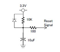
※ Delay time can be calculated 220 milliseconds = 10Kohm(Resistance) X 10uF(Capacitance) X 2.2(Constant Value)
Power Monitor Circuit
There are four voltage monitors(3.3V ・5V ・24V ・24V(CAN)) circuit on the Cabinet Monitor Board.
3.3V and 5V monitor are used 2 lines Op-Amp and 24V ・24V(CAN) monitor are used Analog Photo coupler, because 24V・24V(CAN) power should be isolated.
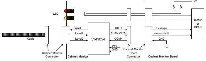
Leakage Sensor
The following shows the block diagram of the leakage sensor.
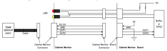
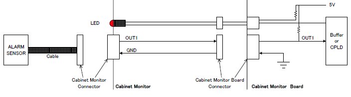
Temperature Sensor
The following shows the block diagram of the Temperature sensor.
Alarm Circshuuit(TANK,PUMP)
The following shows the block diagram of the Alarm Circuit.
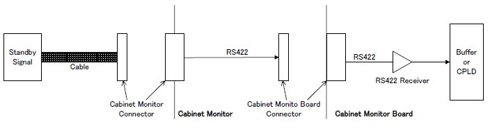
Standby Mode
The following shows the block diagram of the Standby Mode.
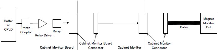
Magnet Monitor Out
The following shows the block diagram of the Magnet Monitor Out.
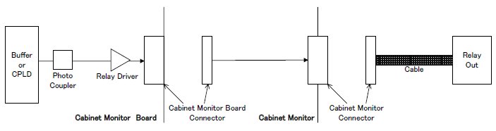
Relay Drive(1-5)
The following shows the block diagram of the Relay Driver. Output signal shall be isolated by photo coupler before relay driver.
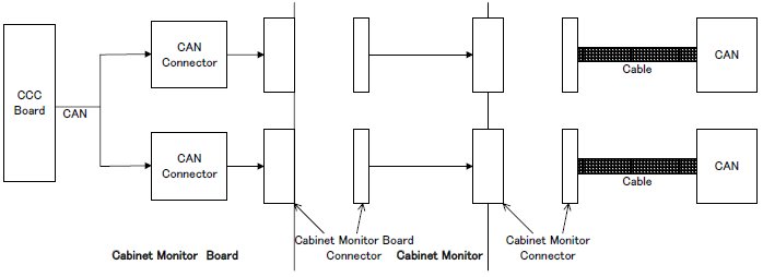
CAN INTERFACE
The following shows the block diagram of the CAN Interface. CAN signal from CCC Board connect with two D-sub 9 pin. And CAN DC 24V also shall be provided.
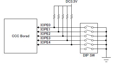
Node-ID DIP Switch
The following shows the block diagram of the CAN Node-ID. The Node ID shall be selectable by this DIP-SW. The Cabinet Monitor Node ID shall be set to 12((H)01100(L)).