
- Optima MR450w BASE 1.5T System Service Methods
- 5690012-2EN Revision 3
- 00000018WIA3026CE20GYZ
- id_131061683.3
- Nov 5, 2020 1:38:56 PM
Probe Tuning and SNR Check Tool (DV24 and later)
Prerequisites
| Required persons | Preliminary requirements | Procedure | Finalization |
|---|---|---|---|
| 1 | 5 minutes | 45 minutes | Not Applicable |
| Item | Quantity | Effectivity | Part number | Manufacturer |
|---|---|---|---|---|
| MRS Phantom (without loader) | 1 | - |
2152220 | - |
| 1.5T TR Split-Top Head Coil | 1 | - |
5182594 | - |
| Curved Adapter Panel for Flat Table (GEM) | 1 | Flat (GEM) table |
5395828 | - |
| Service Filler Panels | 2 | Curved table |
5344577 | - |
| ||||
| Condition | Reference | Effectivity |
|---|---|---|
|
PROBE-S option (M3333WH) is required at site to perform PROBE-S Cal & SNR Check or PROBE-P Cal & SNR Check. | - | - |
|
PROBE-P option (M3333WG) is required at site to perform PROBE-P Cal & SNR Check or PROBE-P SNR Check. | - | - |
About this task
This tool is available in systems with DV24 and later software.
The Probe Tuning and SNR Check Tool is an essential part of conditioning a system for performing spectroscopy, to optimize both SNR and phasing. All tests can be run in one session, and no interaction is needed during the calibration.
There are two Probe/SV pulse sequences: Probe-s and Probe-p.
-
The Probe-s sequence is a version of the stimulated echo acquisition mode (STEAM). This sequence is used for short echo time, single-voxel spectroscopy; that is, TEs shorter than 35 milliseconds.
-
The Probe-p sequence is a version of the point-resolved spectroscopy (PRESS) pulse sequence. The PRESS sequence provides twice the SNR of the STEAM sequence but at the expense of slightly longer minimum TEs.
This document describes two separate hydrogen only spectroscopy (PROBE/SV) procedures:
-
Echo Peak Location calibration (automated PROBE tuning script)
-
PROBE signal-to-noise ratio (SNR) performance test
Scan Setup
About this task
This section provides instructions for centering the phantom. There is no need to run a 3-plane localizer before scanning, because the tool automatically performs a phantom centering check. The tool also has a built in wait time to allow the phantom to settle before scanning.
Procedure
- Set up the table as follows.
-
(For flat (GEM) table) Insert the curved adapter panel into the table.
-
(For curved table on wide bore system) Place the service filler panels under the two cradle top panels.
Figure 1. Table Setup 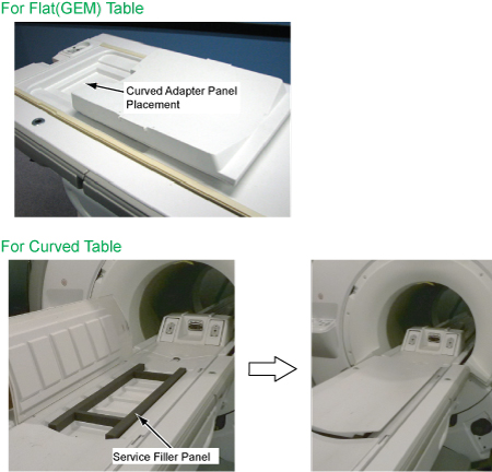
-
- Check the MRS phantom temperature shown on the surface of the
phantom, and record it.
Figure 2. MRS Phantom Temperature 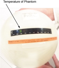
- Position the MRS phantom in the single channel head coil. Do
NOT use the head loader with the MRS phantom. Use foam support pads
for quick alignment to center the phantom in the head coil. Phantom
centering (up/down/left/right/in/out) within 25 mm of the isocenter
in all directions is important.
Figure 3. Position MRS Phantom 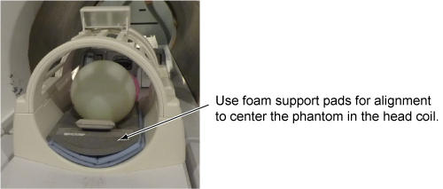
- Start the PROBE Tuning and SNR Check Tool:
- (For non-proprietary service tools) From the Service Desktop, open the Calibration tab, and select Calibration > PROBE Tuning & SNR Check > Click here to start this tool.
The probeTune window appears.
Figure 4. PROBE Tuning and SNR Check Tool 
Reviewing Results
About this task
The probeTune tool also generates log files, which can be viewed from the tool or manually. There are four log files (one for each probe calibration and SNR check). The log files are stored in /usr/g/service/data and are named to indicate which test they result from (for example, *****_CAL.PRB and *****_SNR.PRB). There is no need for data sheets as in previous probe tuning applications. The files are always on the system, and saved on the SaveInfo media (if SaveInfo is performed after calibrations).
Procedure
- To view the log files from the tool, select File >
Open in the probeTune window, select the log file you want
to view, and click Open.
Figure 5. Example of Probe Log File 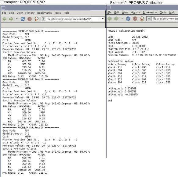
Finalization
Finalization
-
If not performing this test as part of an installation, perform a SaveInfo to save the calibration file.
-
Remove all service equipment from the system, including filler panels if applicable.