Prerequisites
Table 1 . Personnel requirements Required persons Preliminary requirements Procedure Finalization 1 - 2 hours -
Table 2 . Tools and test equipment Item Quantity Effectivity Part number Manufacturer Non-ferrous medium
slotted head screwdriver 1 - - - Non-ferrous medium
Phillips head screwdriver 1 - - -
Table 3 . Consumables Item Quantity Effectivity Part number Manufacturer Marking tape 12 in (305 mm) - - -
Table 4 . Safety
image/svg+xml
image/svg+xml
STRONG MAGNETIC FIELD!
FERROUS HAND TOOLS CAN BECOME DANGEROUS PROJECTILES IN THE
VICINITY OF THE SYSTEM MAGNET.
Do not use any magnetic/ferrous tools or equipment inside
the magnet room.
About this task
Overview
This procedure is for the alignment of two tables dedicated
to one MR suite. You may need to adjust all four wheels on both tables.
Procedure Drive the LPCA through the magnet to the end of the rear pedestal. Undock the patient table and move to an open work area. Remove all lower table covers from all patient tables adjusted
in this procedure (see Patient Table Upper Bellows and Lower Base Side Cover Removal ). Confirm the following: Bridge height is 582–585 mm. Bridge is centered left/right and in/out. Bridge is level (left/right, front/back).
image/svg+xml
image/svg+xml
Personnel INJURY or equipment damage!
The Dock Contains Ferrous Materials and may be pulled into
the magnet bore if securing hardware is removed.
Only loosen the hardware sufficiently to perform adjustments
in this procedure. ensure THE DOCK remains secured TO PREVENT IT FROM
BEING PULLED INTO THE MAGNET BORE.
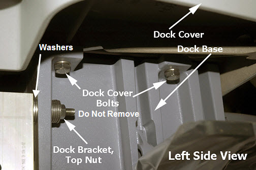
At the rear of the dock, loosen the top and bottom dock bracket
nuts (2 on each side).
Figure 1. Dock Bracket Nuts Get the table removed earlier (first table) and check table
alignment/levelness with the bridge to ensure smooth travel. Adjust
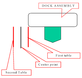
the height as needed according to Leveling Patient Table . Adjust left/right according to Dock Centering and Dock Hook Tension Adjustment Undock the first table and get the second table. Dock the second table and repeat Step 6Step 7 Mark the proper dock alignment (left/right) of the second table
with a second piece of tape. Mark the center point between the two marks. Shift the dock to align with the center point mark.
Figure 2. Marking Center Point Secure the dock by tightening the dock bracket nuts at the rear
of the dock. See Figure 1
Finalization
Dock each table, move the cradle into the bore, and confirm
smooth table travel. If necessary, adjust the table height (see Table Top Height Adjustment ).