- Topic ID: id_16157540
- Version: 4.0
- Date: May 24, 2022 2:04:01 AM
X-Ray Tube Replacement
Prerequisites
Overview
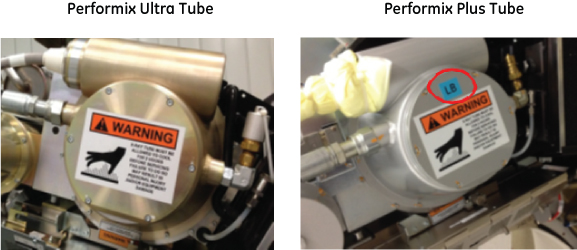
This document provides the necessary steps to replace and configure the x-ray tube for imaging. There are two tube types: Performix Ultra_(BB) tube (D3885T/D3886T) and Performix Plus_(LB) tube (D3889T/D3890T). This procedure only defines same tube type replacement workflow.
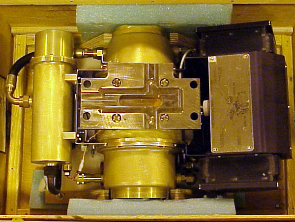
Figure 1. Tube Removal Diagram
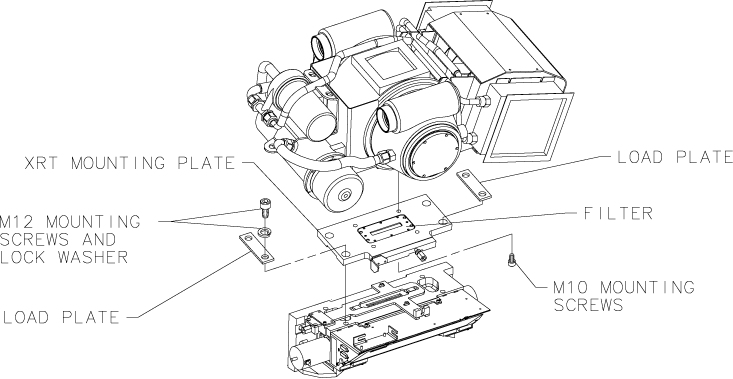
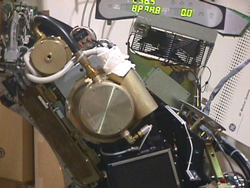
Figure 2. Performix Ultra Tube and Plus Tube Appearance Difference
1 Data Entry
Procedure
- Open SERVICE DESKTOP.
- Enter the data of the new tube:
- Select REPLACEMENT.note: Perform Tube Installation Certification, if required. Refer to SmarTube™ Setup.
- Select TUBE CHANGE.
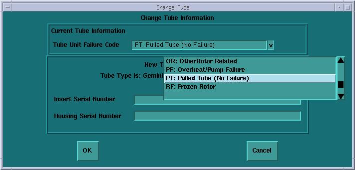
- Select NEWTUBE CONFIG, select a proper
Tube Unit Failure Code (reason for tube replacement), Insert Serial
#, and Housing Serial # of a new tube, then click on OK.
Figure 3. Change Tube Information Screen
- Select REPLACEMENT.
2 Old Tube Removal
Procedure
 danger
- danger
- Remove and set aside gantry side, top and front covers.
Refer to Replacement > Gantry > Enclosure > Cover Removal Procedure.
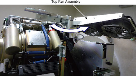
- Slide out the gantry rear cover, and rotate the top fan assembly
outward.
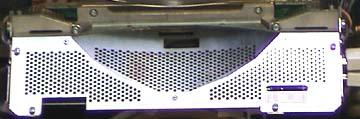
Figure 4. Top Fan Assembly
- Remove the M12 screws holding support bracket for the right
front gantry cover and set the assembly aside. It may be necessary
to tilt the gantry back to remove the third bolt (not normally installed).
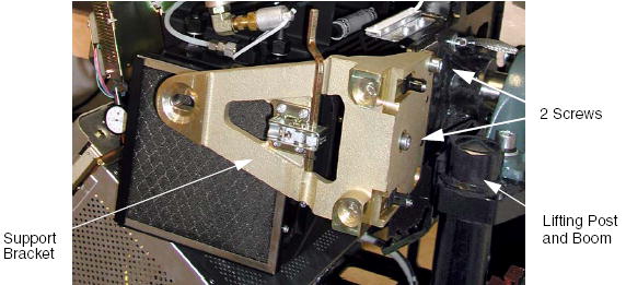
Figure 5. Right Front Gantry Cover Support Bracket
- notice
- Turn off the AXIAL DRIVE ENABLE, HVDC ENABLE, and 120VAC switches.
- Turn off facility power to PDU and lockout/tagout according to lockout/tagout procedure.
- Rotate the Gantry until the x-ray tube reaches the 3 o’clock
position.note: It may be easier to loosen the M12 tube mounting bolts with the tube at about the 2 o’clock position before locking the tube at the 3 o’clock position. Simply loosen the tube mounting bolts one half (1/2) turn. Do not remove the bolts yet.
Figure 6. Tube Angle to Loosen and Torque M12 Screws
- warning
- notice
- Engage gantry rotational lock, and check that the gantry is securely locked by attempting to rotate the gantry by hand.
- warning
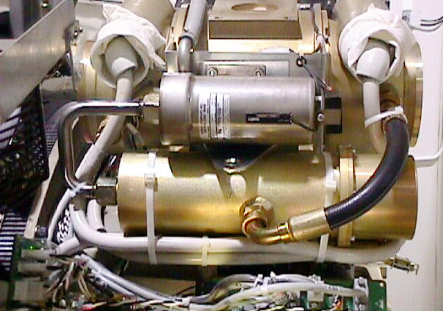
- Disconnect the 12 pin tube I.D. system cable, from the top of
the tube unit (J1). Reference Figure 7
Figure 7. J1 and J2 location
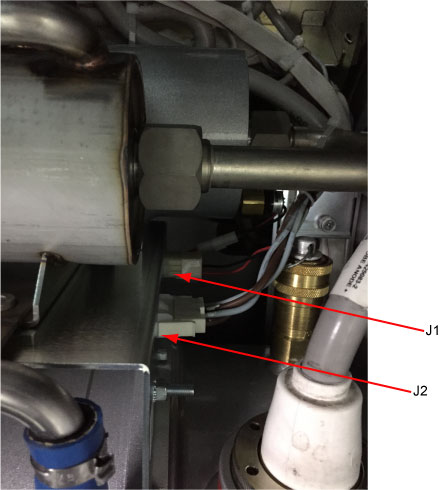
- Disconnect the 4 pin mate-n-lock pump and fan power system cable (J2). Reference Figure 7
- Remove the anode and the cathode cable:
-
Carefully cut tie-wraps securing HV cables. Note HV cable routing.
-
Loosen each cable’s locking ring with the spanner wrench.
-
Pull each cable terminal out of its receptacle.
-
Ground the end of the cables to the Gantry frame.
-
Wipe up any oil that drips from the cable terminal.
-
Use paper towels to soak up any oil in the wells.
-
Cover receptacles with caps.
-
- caution
- note: It may be easier to tape the socket to the extension. This will prevent the socket from being dislodged on the tube radiator assembly(For Performix Plus_LB tube only) Disconnect Smart ID cable (P/N 5339643) connector J1 from Tube.
- Insert the lifting post, boom and chain hoist. Reference Figure 5
- The XRT is attached to the Collimator with a Tube Mount Bracket Assembly. Remove the mounting plate & XRT from the Collimator by removing the four M12 cap screws and lock washers, and two load plates, with a hex socket driver. With your hand, reach behind the radiator to the screws from either side of the XRT center section while removing the bolts with two 12-inch extensions (24 inch length) on a ratchet. Throw these M12 bolts and washers away, as they should not be reused.
- Carefully swing the tube clear of the gantry.note: Be careful not to damage the fragile copper filter or lead shield in the mounting plate for the next step.
- warning
- If the replacement tube has a mounting plate attached (see Figure 8), DO NOT REMOVE IT. SkipStep 16 and Step 17.
Figure 8. Tube Shipped with Mounting Plate Attached
- notice
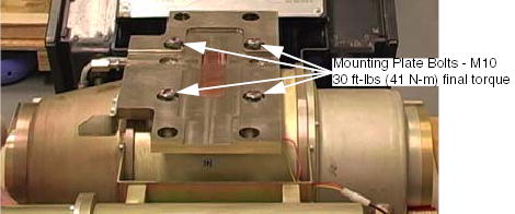
- If the replacement tube does NOT have a mounting plate attached, remove the mounting plate by removing the four M10 (P/N 46-328416P20) hex head screws. Throw these bolts and washers away, as they should not be reused.
- If new tube has no mounting plate attached, inspect the copper
filter. The copper filter should be clean, dent and scratch free:
-
If contamination is visible (see Figure 9), proceed to Collimator Cleaning Procedure.
-
Discoloration is acceptable.
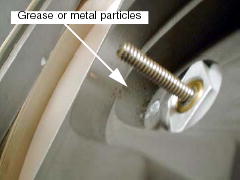
Figure 9. Extremely Contaminated Copper Filter
 note:
note:Perform the following inspection before installing the new tube unit. Also look at the tube side of the copper filter when you are swapping the interposer plate.
The following tools are required for this inspection procedure:
-
Phillips #2 Screwdriver
-
Flat blade Screwdriver
-
Bright Flashlight
-
- Inspect the Bowtie Filter. It is possible that the Bowtie Filter
is contaminated and the Primary Copper Filter is not contaminated.
- Remove the Collimator Control Board Sheet Metal Cover. See Figure 10.
Figure 10. Collimator Control Board Cover
- warning
- notice
- With power removed from the gantry, use a flat blade screwdriver
and position the bowtie filter assembly so it is visible through the
input port or tube side of the collimator assembly.
-
CCW will move the filter into the beam. See Figure 11.
-
Do not move the filter back to the home position.
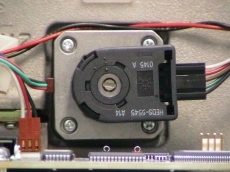
Figure 11. Filter Position Adjuster
-
- Using a flashlight, inspect the bowtie filter for contamination.
Reference Figure 12.
Look through the input port or tube side of the collimator.
If contamination is visible, proceed to Collimator Cleaning Procedure.
Figure 12. Contaminated Bowtie Filter


- Remove the Collimator Control Board Sheet Metal Cover. See Figure 10.
|
|
 |
|
|
3 New Tube Installation
Procedure
- danger
- danger
- warning
- Allow the tube unit to warm to room temperature before you install it.
- Remove all package from the new tube.
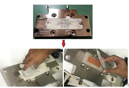
- Remove the plastic protective cover and the thick paper cover from the tube copper filter.
Figure 13. Remove the Plastic protective Cover and Paper Cover
- warning
- If the new tube has a factory installed mounting plate, DO NOT REMOVE IT. Skip to Step 6.
- warning
- Attach the mounting plate from the old tube using new M10 x
25mm bolts provided with the tube. Do NOT use Loctite.
-
Finger tighten all four (4) bolts
-
Torque all four (4) bolts to the following specification:
This seats each bolt, enabling you to visually ensure that the mounting holes are not stripped while applying final torque.
Apply final torque on all four bolts:
Figure 14. Tube and Mounting Plate
-
- notice
- Re-check facility power and make sure it is off.
- warning
- Use the hoist to lift the new tube unit:
- Position the tube on the gantry: The “crosses” on
the mounting plate and on the collimator should fit in perfectly when
the tube is aligned properly.note:
-
To ease installation, fasten the top pressure plate to the rotating structure first. Then attach the bottom pressure plate.
-
Use new bolts and washers from tube crate. Make sure to select the proper bolts. There are instructions in the crate, and on the tube itself.
-
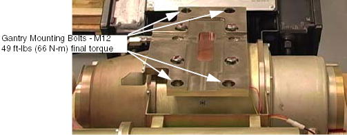
- Fasten the lower and upper and pressure plates to the rotating
structure with the four M12 (50 mm) bolts, and set pre-load torque
to:
- Set final torque to:
Figure 15. Tube and Mounting Plate
- Position the tube on the gantry: The “crosses” on
the mounting plate and on the collimator should fit in perfectly when
the tube is aligned properly.
- Attach the tube I.D. cable to the 12 pin mate-N-Lock connector (J1) on top of the tube. Reference Figure 7
- Attach the tube pump and fan power cable to the 4 pin mate-N-Lock connector (J2). Reference Figure 7
-
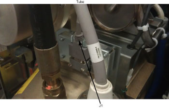
(For Performix Plus_LB Tube only) Install Smart
ID cable (P/N 5339643) connectors. (see Figure 16)
J1 Connector (<-> Tube)
Figure 16. Smart ID cable connection
- Fasten the grounding strap to the 1/4-20 ground stud on top of the tube unit.
- Remove the plastic cap plug from each cable receptacle on the
tube unit.note: Take care not to lose the rubber quad rings for the High Voltage cables.
- Lightly wet the new rubber quad ring with transformer oil.
- Return the quad ring to its slot at the top of the receptacle retaining ring.
- Pour transformer oil into the receptacle approximately 13 ml (reference only, please adjust the oil amount as necessary).note: DO NOT use the syringe in vertical position, this will result in air bubbles which increase the chances of the high voltage breakdown.
Figure 17. Filling Receptacle

- notice
- Be sure to route the HV cable as shown in Figure 18.
Figure 18. HV Cables Properly Routed and Secured
- Align the cable terminal orienting key with the notch in the
receptacle.
- notice
- Slowly insert the cable, to engage the connector pins, and seat the cable in the receptacle.note:
After installing the cable to the receptacle, confirm the transformer oil is spilled over a little from the receptacle as shown in Figure 19.
If the transformer oil is inappropriate amount, adjust the oil amount as necessary.
Figure 19. Appropriate Amount of Transformer Oil
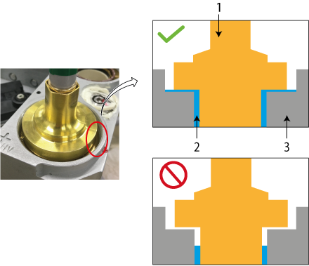
1 HV Cable 2 Transformer Oil 3 Receptacle -
Tighten the cable locking ring.
note: Use service wrench to turn the threaded ring ¼ to ½ of a full turn after the gap is closed and friction is felt by hand. - notice
Rotate the cable strain relief for a clean cable dress.
-
- Carefully wipe up all excess oil.
- Secure HV Cables using large tie-wraps, as shown in Figure 18.
- Disconnect hoist from tube and boom.
- Remove the post and boom from the gantry. Reference Figure 5.
- Check for oil leaks:
-
Wrap rags or paper towels around the cable horns, and tape them into place.
-
Manually rotate the tube to the 6 o’clock position.
-
Return the tube to the 3 o’clock position
-
Remove the toweling and wipe up all excess oil.
-
Wipe off the cable horns, locking rings and strain reliefs with an alcohol-dampened rag.
-
Repeat with a dry rag.
-
Wrap the cable strain reliefs and locking rings with a single layer of absorbent paper tissue. You can use two inch wide strips cut from a paper napkin.
-
Wrap the bottom edge of the paper around the top end of the cable horn, and tape it in place.
-
Extend the top edge of the paper over the top of the locking ring, and tape it to the plastic cable strain relief.
-
Remove paper after leak check.
-
- If oils leaks are found, tighten the locking ring slowly until there is no leakage, paying attention to not over tighten.
- Install the right gantry front cover bracket. Reference Figure 5.
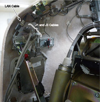
- Reattach front cover J1, J3 and LAN cables.
Figure 20. Front Cover Cables
- Restore system power at the main disconnect panel.
- Turn on gantry 120 VAC, HVDC ENABLE and AXIAL DRIVE ENABLE on the service switch panel. Wait at least 10 minutes to warm up the filament.
- Reset the system:
- Open SERVICE DESKTOP.
- Select SYSTEM RESETS.
- Select SCAN, then RUN.
- Verify tube types match before proceeding:
- Select ERROR LOGS.
- Select TUBE USAGE.
- Select SUMMARY.
|
|
|
4 Finalization
Procedure
- Checklist
- New mounting bolts and washers are used for mounting the tube; old mounting bolts and washers are discarded.
- Proper torque specifications are followed for all fasteners (see Torque Wrench Information).
- Tie-wraps and cables are in place.
- Perform Tube Installation Certification, if needed. Refer to SmarTube™ Setup.
- If you have a system with the detector and collimator previously
aligned before this tube change and there are no image quality issues,
use the “Quick Tube Change” procedure below in the order
described.
- Reset TnT Data in Jedi Generator Tool (16, Ultra, Plus))
- Tube Z-Align.
- ISO Alignment Procedure
- Meter Verification (16, Ultra, Plus)
- HV Tank Feedback Resistor Verification (bleeder test)
- Filament Calibration
-
HHS Scans
Tube Usage Information is found on the Common Service Desktop following path:
Error Logs>Tube Usage>Details.
- Gantry Balance Procedure (LS16, Ultra & Plus)
- Hot ISO Alignment
- New Tube Configure
- Turn OFF HVDC ENABLE, AXIAL DRIVE ENABLE and 120VAC switches on the Service Switch panel.
- Install the gantry front cover, rear cover, top cover, left side cover and scan window.
- Turn ON HVDC ENABLE, AXIAL DRIVE ENABLE and 120VAC switches on the Service Switch panel.
- Press ESTOP RESET on the Service Switch panel, and wait until scan hardware is reset.
- Install the gantry right side cover.
- Z-Slope
- DAS Gain Calibration
- Collimator Calibration
- Detailed Cals
- N Number Check
- Image Series
- Gantry Rotation Safety Check
- Save System State
- If you cannot follow the quick tube change procedure for any
reason, perform the retest steps below in the order described.
- Reset TnT Data in Jedi Generator Tool (16, Ultra, Plus))
- Plane of Rotation (POR) Alignment
- Beam on Window (BOW) Alignment
- CBF/SAG Alignment Process
- ISO Alignment Procedure
- Meter Verification (LS16, Ultra & Plus)
- HV Tank Feedback Resistor Verification(bleeder test)
- Filament Calibration
-
HHS Scans
Tube Usage Information is found on the Common Service Desktop following path:
Error Logs>Tube Usage>Details.
- Gantry Balance Procedure (LS16, Ultra & Plus)
- Hot ISO Alignment
- Turn OFF HVDC ENABLE, AXIAL DRIVE ENABLE and 120VAC switches on the Service Switch panel.
- Install the gantry front cover, rear cover, top cover, left side cover and scan window.
- Turn ON HVDC ENABLE, AXIAL DRIVE ENABLE and 120VAC switches on the Service Switch panel.
- Press ESTOP RESET on the Service Switch panel, and wait until scan hardware is reset.
- Install the gantry right side cover.
- Z-Slope
- DAS Gain Calibration
- Collimator Calibration
- Detailed Cals
- FastCal
- Image Series
- Gantry Rotation Safety Check
- Save System State