- Topic ID: id_11038753
- Version: 6.0
- Date: Dec 22, 2021 11:23:38 PM
Meter Verification
Prerequisites
Overview
Objective: Verify that the internal mA meter are functional. If the meter is not functional, the inverter cannot be used in the system.
-
Connect meter to test points and a load resistor for the tube current
-
Perform x-ray exposures
-
Take measurements
Procedure
- Perform warm-up scans, if the x-ray tube is cold.
- Remove gantry right side cover if it's not already removed.
- Stop the rotor of X-ray tube in case of Liquid Bearing Tube before HVDC off. Refer to Liquid Bearing Tube Rotor stop procedure for details.
- Turn off all three service switches on the Service Switch Panel (AXIAL DRIVE ENABLE, HVDC ENABLE, 120VAC).
- Rotate the gantry such that the power unit is in the 2 O'clock position.
- Remove the Inverter cover. If there are two covers on the inverter, remove the larger of the two, nearest the cradle.
- Lock the gantry in position, using the rotational lock. Ensure that gantry rotation is locked by attempting to rotate the gantry by hand.
- Attach a protective ESD wrist strap.
- notice
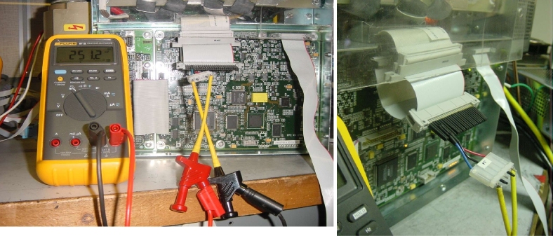
- Connect a 'JEDI Shunt Measurement Tool' and a multi-meter (see Figure 1, Figure 2, and Figure 3)
- Disconnect the flat cable from J1 connector on the kV Control board.
- Connect J1 of the JEDI Shunt Measurement Tool to the J1 connector on the kV Control board.
- Connect the flat cable to J3 of the JEDI Shunt Measurement Tool.
- Connect a digital multi-meter (DMM/DVM) to J4 of the JEDI Shunt Measurement Tool.
Figure 1. JEDI Shunt Measurement Tool
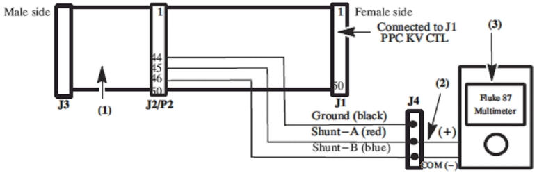
Figure 2. Connection of the JEDI Shunt Measurement Tool
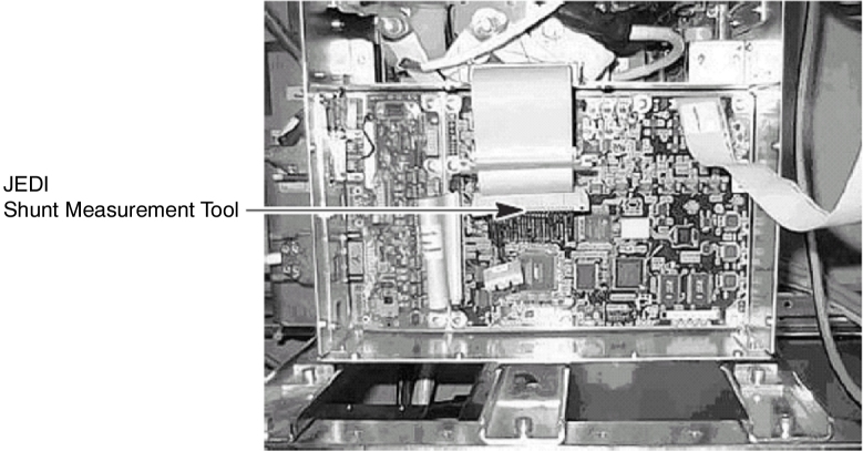
Figure 3. Connection of the Multi-meter
- Measure, and fine the value of shunt resistor :
- Set the multi-meter to the Ohmmeter function.
- Connect the multi-meter between Ground (black pin) and Shunt A (red pin) on the external tool.
- Record the Shunt A resistor value with second decimal places (ex. 5.48 ohms. measured around 5 ohms).
- Connect the multi-meter between Ground (black pin) and Shunt B (blue pin) on the external tool.
- Record the Shunt B resistor value with second decimal places (ex. 0.53 ohms. measured around 0 ohm).
- Verify that the value of shunt resistor is the following:
Shunt A - Shunt B = 5Ω ± 2%
- Connect the multi-meter between Shunt A (red pin) and Shunt B (blue pin) on the external tool.
- Set the multi-meter to the DC voltage measurement mode.
- Turn ON the 120VAC and HVDC ENABLE on the Service Switch Panel.
- Clear the E-Stop condition by pressing the DRIVES RESET button on the Service Switch Panel.
- Wait about 2 minutes for the gantry display to reset. No flashing lights on the gantry display should indicate this.
- On the Service Desktop, select [DIAGNOSTICS], then [KV & MA (X-RAY)].
- Verify the following scan parameters:
-
X-Ray test type = manual
-
Gantry = Disabled
-
Exposure time = 2s
-
No of scans = 1
-
Focal Spot = Large
-
kV = 120kV
-
mA = 50mA
-
- Press RUN and take scan.
- Record the ending voltage on meter to one decimal place(ex. 251.2mV). If this accuracy cannot be obtained, change range on meter and redo scan.
- Record Console displayed mA value.
- Repeat the measurement for 200mA.
- The difference between mA measured (= [measured voltage (mV)] / [shunt resistor value] ) and the displayed mA on console should be within ±2% of the requested mA.
- Stop the rotor of X-ray tube in case of Liquid Bearing Tube before HVDC off. Refer to Liquid Bearing Tube Rotor stop procedure for details.
- Turn off all three service switches on the Service Switch Panel (AXIAL DRIVE ENABLE, HVDC ENABLE, 120VAC).
- Remove the 'JEDI Shunt Measurement Tool' from the generator.
- Verify mA test point accuracy :
- Set the multi-meter to the DC voltage measurement mode.
- Connect red signal lead from meter to MA_N (TP20) and black common lead to MA_GND (TP19) on the CT Interface board.
- Turn ON the 120VAC and HVDC ENABLE on the Service Switch Panel.
- Clear the E-Stop condition by pressing the DRIVES RESET button on the Service Switch Panel.
- Wait about 2 minutes for the gantry display to reset. No flashing lights on the gantry display should indicate this.
- Launch [KV & MA (X-RAY)] tool.
- Verify the following scan parameters:
-
X-Ray test type = manual
-
Gantry = Disabled
-
Exposure time = 2s
-
No of scans = 1
-
Focal Spot = Large
-
kV = 120kV
-
mA = 50mA
-
- Press RUN and take scan.
- Record the ending voltage on meter to three decimal place (ex. -0.503 V). If this accuracy cannot be obtained, change range on meter and redo scan.
- Record Console displayed mA value.
- Repeat the measurement for 200mA.
- Multiply the meter reading by minus 100. ([TP measured mA] =
[measured voltage (V)] x (- 100)).
* TP measured mA and displayed mA on console must be within ±4% of the requested mA.
- Stop the rotor of X-ray tube in case of Liquid Bearing Tube before HVDC off. Refer to Liquid Bearing Tube Rotor stop procedure for details.
- Turn off all three service switches on the Service Switch Panel (AXIAL DRIVE ENABLE, HVDC ENABLE, 120VAC).
- Verify kV test point accuracy.
- Set the multi-meter to the DC voltage measurement mode.
- Connect red signal lead from meter to KV_N (TP18) and black common lead to KV_GND (TP17) on the CT Interface board.
- Turn ON the 120VAC and HVDC ENABLE on the Service Switch Panel.
- Clear the E-Stop condition by pressing the DRIVES RESET button on the Service Switch Panel.
- Wait about 2 minutes for the gantry display to reset. No flashing lights on the gantry display should indicate this.
- Launch [KV & MA (X-RAY)] tool.
- Verify the following scan parameters:
-
X-Ray test type = manual
-
Gantry = Disabled
-
Exposure time = 2s
-
No of scans = 1
-
Focal Spot = Large
-
kV = 80kV
-
mA = 50mA
-
- Press RUN and take scan.
- Record the ending voltage on meter to second decimal place( ex. -3.96V) . If this accuracy cannot be obtained, change range on meter and redo scan.
- Record Console displayed kV value.
- Repeat the measurement for 100kV, 120kV, 140kV.
- Multiply the meter reading by minus 20. ([TP measured kV] =
[measured voltage(V)] x (- 20)).
* TP measured kV must be within ±3% of requested kV.
* TP measured kV and Displayed kV on console must be within ±2% of requested kV.
 |
Finalization
- Replace inverter and gantry covers if necessary.
- All the measurements should be within the limits.
- Record the results on the HHS data sheet.