- Topic ID: id_11038839
- Version: 2.0
- Date: Jan 30, 2019 9:43:12 PM
Gantry Balance Procedure (16, Ultra, Plus)
Prerequisites
This procedure should be performed any time the rotating gantry is serviced. It is intended to:
-
Check or create sensitivity matrix
-
Balance the gantry in both static and dynamic vectors.
Gantry balance weights information, refer to below Table.
(For 78 degree weights) Three 78 degree weights (2378669-2, shipped with shipping collector) on site, if need more 78 degree weights to adjust gantry balance, please order 2378668-2 and 2378669-2 according the actual needs.
(For 180 degree weights) If the quantity of 180 degree weights (shipped with shipping collector) can not meet gantry balance adjustment, please order 2342895-2, 2342895-3 and 2317863 according the actual needs.
Procedure
- notice
- notice
- Read and observe the Notices above, where required.
Figure 1. DAS Debris Shield
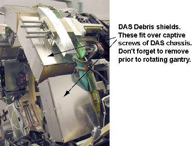
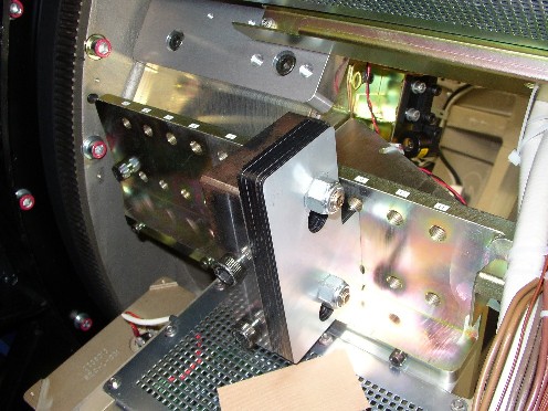
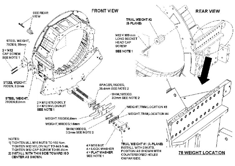
Figure 2. Balance Weight at 78-degree Location
 note:
note:You may not have all plate types installed on your gantry depending on what is needed to balance your gantry.
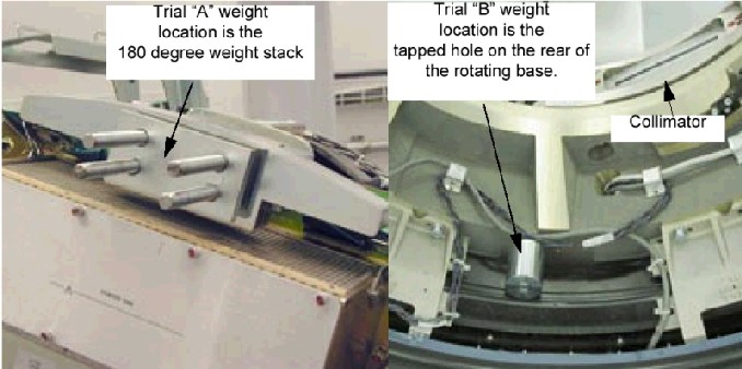
Figure 3. Trial Weight A and B mounting locations
- Position the table to its lowest position.
- Remove the gantry side, top, front and rear covers.
- Launch the Gantry Service Balance from the Service Desktop,
Calibration tab.
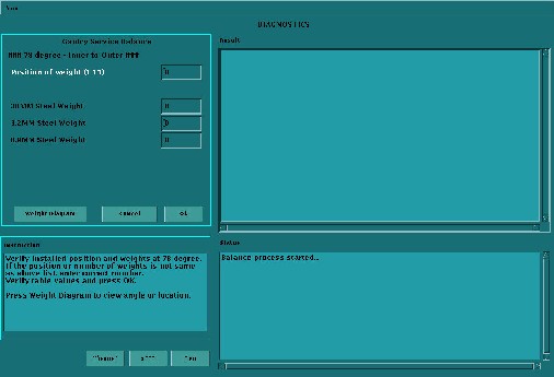
Figure 4. Sample Gantry Service Balance GUI
- Select Run to start the gantry balance procedure.note:
Follow the on screen instructions exactly as stated. Failure to follow the steps may result in having to start the procedure from the beginning.
- If the sensitivity matrix does not exist or the gantry is out
of balance, the program will ask you to enter the current weight configuration
prior to performing the steps to generate a new sensitivity matrix.
See Figure 7 for example of entries for 78° weight stack.
The 180° weight stack appears in the similar manner.note:
There is a weight diagram available via the "Weight Diagram" button in the GUI. See Figure 5. The diagram shown on the product supersedes any listing in this procedure. Pay close attention to Note 2 for the 180° 25.4mm spacer and 3.2mm shim orientation. The holes are shifted to one side and should be installed with the holes closest to the edge on the bottom near the DAS.
Figure 5. Sample Weight Diagram
Refer to Figure 3 for Trial weight placement during sensitivity matrix generation process. Program will ask you to place each of the two trial weights one at a time during the process. Trial weight A at 180° position must be installed over top of the existing weight stack nuts such that existing nuts are in recessed holes of trial weight. Install trial weight as shown in the Weight Diagram on the system. This is the configuration and weight components expected by the program. See also Figure 6.
Figure 6. Installation of Trial Weight A
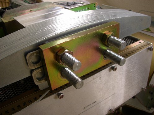
Figure 7. Request for existing weight configuration
 note:
note:The order of the balance weights as installed on the gantry is very important. An entry of zero is valid if the particular weight type is not currently installed.
The program will ask or instruct the user about the number of specific weights in both 78 and 180-degree locations. The order is labeled as "inner to outer" with inner referring to weights closest to the gantry (rear) and outer as towards the table (front).
- Follow the steps as stated in the "Result" portion of the GUI
screen as you proceed through the Gantry Balance procedure. Those
steps will not be included here as they may change from release to
release of the product.
See Table 3 for example questions and messages that may come up depending on system status and answers to other questions during program execution. Message wording may not be exactly the same as shown below.
- When the Gantry Balance procedure indicates a passing result
save the updated configuration information and exit the program.

 warning
note:Refer to "Gantry Service Balance Theory" for explanation regarding torque as it applies to this area.
- Make sure to torque all fasteners as instructed.
Be sure the nuts on four threaded rods are tight in the 180-degree location. Use the Torque wrench ordered from the tool depot to tighten nuts to 160N-m (118 ft-lbs). This torque wrench is a 1/2" drive to match the deep well socket and is capable of 250 ft-lbs.
In the 78-degree location, tighten the two M12 nuts to 44.5N-m (32.8 ft-lbs), and tighten the two M12 cap screws to 66.4N-m (48.9 ft-lbs).
Be aware that adjacent nuts might loosen when a nut is tightened due to the springiness of the stack. Use a diagonal type pattern (similar to tightening tire lug nuts) to tighten the nuts and go back to verify all are still torqued properly when complete. Refer to Gantry Balance Theory for further discussion regarding the importance of torque on the weights.
 |
|
Finalization
- Assemble gantry.
- Perform FASTCAL and ensure no pop-up windows occur and gesyslog is error free.