- Topic ID: id_11038969
- Version: 4.0
- Date: Nov 27, 2020 2:06:59 AM
Beam on Window (BOW) Alignment
Prerequisites
The objective of this procedure is to put the Detector in the correct position, assuming the tube is already in the correct position. This makes sure the X-ray Flux does not miss the Detector.
Figure 1. BOW Alignment Process Flow
1 For Tube Change Only
Wait 90 minutes if the new tube had more than 25 Kilo Joules of energy input, [KV x mA x Sec ÷ 1000] within the last 30 minutes prior to the start of system alignments. If a tube heat soak has been performed you must wait a minimum of 6 hours before system alignments can be performed.
2 Accessing the Software
Procedure
- Select SERVICE DESKTOP.
- Select CALIBRATION.
- Select BOW ALIGNMENT
Figure 2. Screen Shot for Beam on Window Alignment (BB Tube)
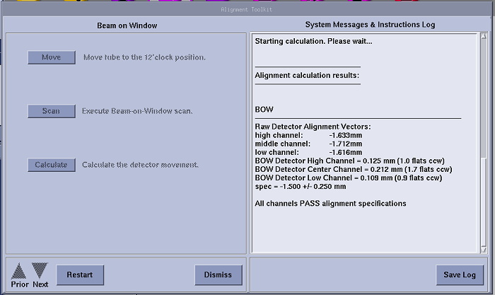
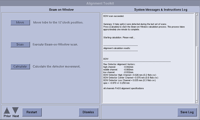
Figure 3. Screen Shot for Beam on Window Alignment (LB Tube)
 note:
note:Above illustrations are only GUI examples, each product should have its correct specs shown on the system.
For CT540, the specs should be:- BB Tube: -1.500+/-0.250 mm
- LB Tube: -0.970+/-0.250 mm
3 Adjustment Procedure
Procedure
- Select MOVE to send the tube to the 12 o’clock position.
- Acquire a Beam on Window Scan.
- Select CALCULATE and make adjustments as indicated by the program.
- Remove the rear gantry cover if necessary.
- Refer to Figure 4. Loosen the cap-head screws, located
at each end of the detector (total of two cap-head screws).
Figure 4. Detector Cap-head Screws
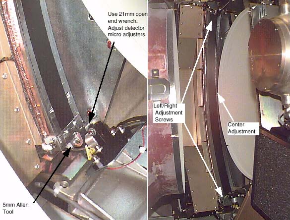 note: CW (clockwise) turns move the detector toward the mounting plate. CCW (counter-clockwise) turns move the detector away from the mounting plate. Right=Low Chnl, Center=Medium Chnl, Left=High Chnl.
 - Loosen the middle nut (jam nut) with a 10mm wrench. Make adjustments as requested by software.
- Acquire a Beam on Window Scan, then select CALCULATE.
- If the adjustments pass the calculation, proceed to the next step, otherwise return to step 2.
- Use the appropriate step depending your system type below.
-
(For 16 Slice Detector)
Torque outer and center screws first to 50% of final torque value as shown inTable 4 and Table 5.
After all screws have been seated using the initial torque setting, apply the final torque as shown inTable 6 and Table 7.
note: The specs for BOW are checked by the software. If an adjustment is needed for the first BOW scan, make adjustments per procedure. In the verification scan, the spec is different than the software version because the tube is warm.
-
(For 16 Slice Detector)
4 Finalization
No finalization steps.