
- Discovery MR750 3.0T System Service Methods
- 5690009-2EN Revision 4
- 00000018WIA3017D030GYZ
- id_123748441.8
- Jan 27, 2022 6:50:31 PM
Replacing the cradle latch–curved table
Replace the cradle latch housing for a 32-channel system or a 16-channel system.
Prerequisites
| Personnel requirements | |||
|---|---|---|---|
| Required persons | Preliminary requirements | Procedure | Finalization |
| 1 | - | 45 minutes | 5 minutes |
| Tools and test equipment | ||||
|---|---|---|---|---|
| Item | Quantity | Effectivity | Part number | Manufacturer |
| Non-Ferrous Service Tool Kit | 1 | - |
5112581 | - |
| Replacement parts | ||||
|---|---|---|---|---|
| Item | Quantity | Effectivity | Part number | Manufacturer |
| Cradle Latch Cable (cut to 1500 mm) | 1 | - |
Refer to FRU Manual | - |
| Cradle Latch Housing | 1 | - |
Refer to FRU Manual | - |
| ||||
About this task
Overview
This procedure gives the steps for replacing the cradle latch housing for a 32-channel system or a 16-channel system. The 16-channel system does not allow for the complete removal of the cradle assembly.
Removing the cradle latch housing
Procedure
Lower the table lock safety bar. Lower the table and verify that all its weight is resting on the lock bar.Warning 
Figure 1. Table lock safety bar 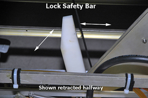
- Hold down the cradle latch block and press the cradle release button at the same time.
Figure 2. Cradle removal 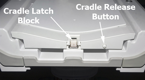
- Push in the right actuator on the table front base.
Figure 3. Table front base 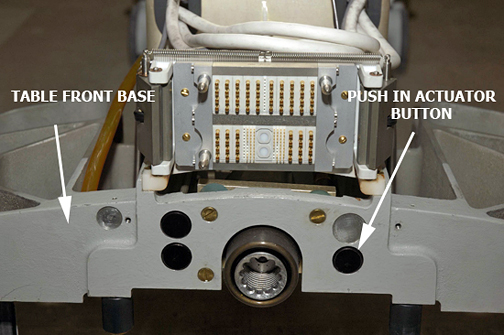
- For a 32-channel system, do one of the following:
Figure 4. Propping up back of cradle 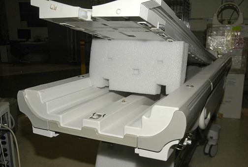
- With the cradle raised, remove the cable covers at the head of the cradle, held by two screws on each side.
Figure 5. Cable cover removal 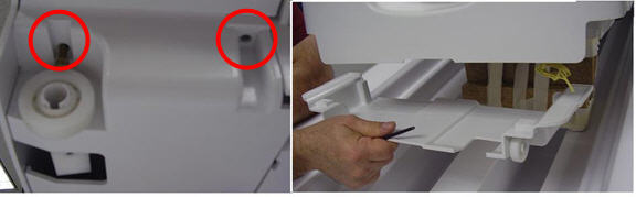
- Untie the knot in the Kevlar cord. A scribe or other tool may be needed to loosen the knot.
Figure 6. Kevlar cord knot and release lever screw 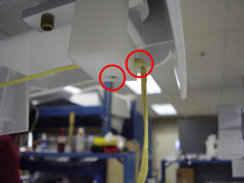
- Pull out the rivet from the side of the release lever, noting that the Kevlar cord is positioned over the rivet.
Figure 7. Release lever rivet 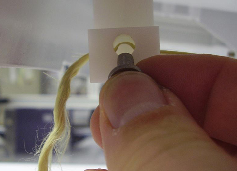
- Pull the Kevlar cord through the release lever approximately 6 inches. DO NOT pull the cord out of the release lever completely.
Figure 8. Loosen Kevlar cord 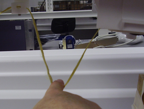
- Remove the blocks or other structure used to elevate the cradle. Put the cradle back down so that there is approximately 18 inch (46 cm) overhang at the foot of the table.
Figure 9. Cradle position 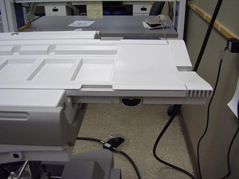
- Pull the cradle hinge pin out. The cradle hinge pin can only be removed on the left side of the table. Push out the pin on the side using large needle nose pliers.
Figure 10. Remove hinge pin 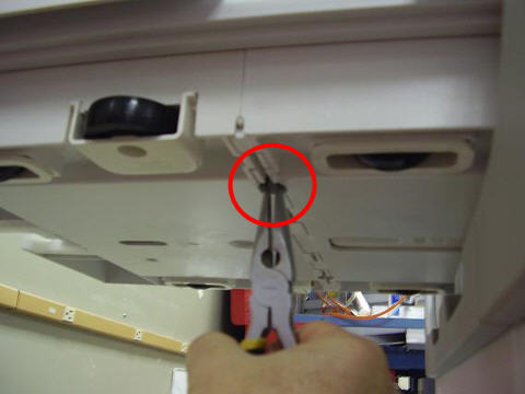
- After the hinge pin is removed, slide the front cradle section out.
Figure 11. Extend cradle section 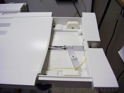
- Remove the rubber latch spring.
Figure 12. Remove latch spring 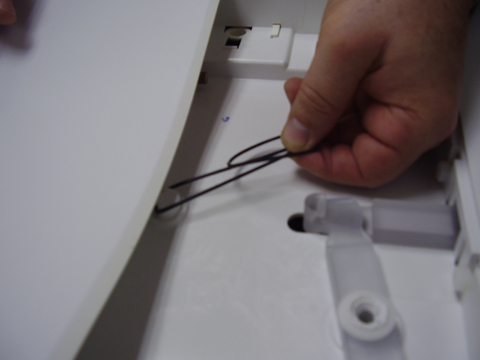
- Remove the two nylon screws.
Figure 13. Remove nylon screws 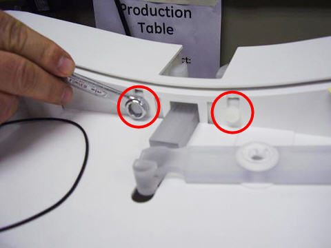
- Unhook the release lever from the release bar. This is accomplished by pulling the release bar, lifting slightly, and away from the lever. The latch assembly will then be free to pull down and remove.
Figure 14. Remove release lever 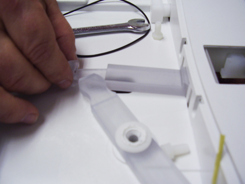
- Remove the two plastic screws on top of the removed latch assembly. Then remove the latch blocks. Note the orientation of the angles on the latch blocks for installing the new cradle latch assembly.
Figure 15. Cradle latch disassembly 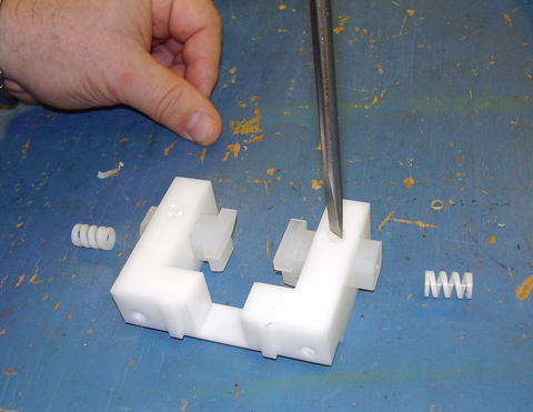
Installing the cradle latch assembly
Procedure
- Install latch blocks and plastic screws into the new latch assembly. Make sure the screws go through the slots on the latch blocks. When assembled properly, the latch blocks will have limited side-to-side movement but will not fall out of the assembly.
Figure 16. New cradle latch assembly 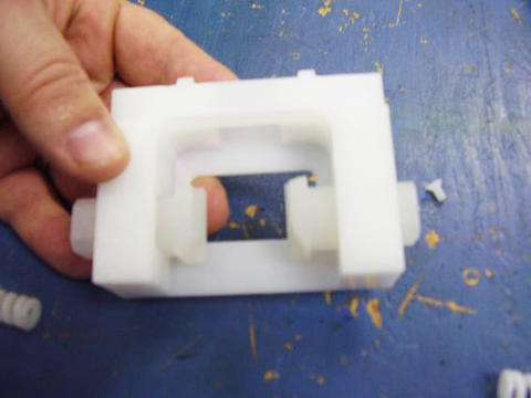
- After the new cradle latch assembly is assembled, position the flat side of the latch blocks on the bottom.
Figure 17. Latch block orientation 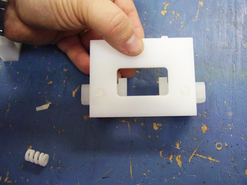
- Install the new cradle latch assembly into the table.
Figure 18. Latch installation 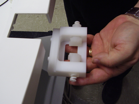
- Replace the rubber latch spring.
Figure 19. Reinstall latch spring 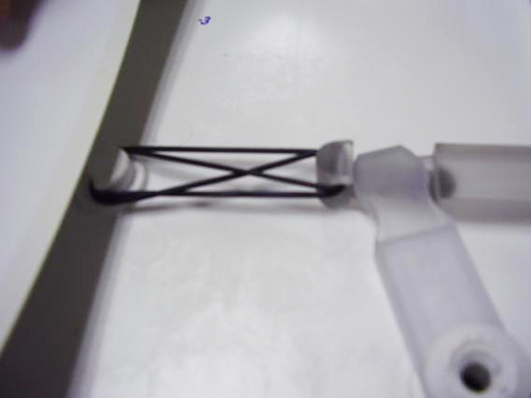
- Put the front cradle plunger in position on the cradle rod.
Figure 20. Cradle rod re-Installation 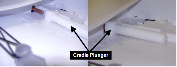
- Slide the cradle back together. Install the hinge rod. A hammer may be required to tap the hinge rod back into position.
Figure 21. Hinge pin installation 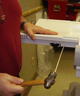
- Insert the rivet back into the release lever, making sure that the Kevlar cord is routed OVER the rivet when it is installed as shown in Figure 7. Pull the Kevlar cord taut without causing the release bar to protrude into the latch housing. The lever should be pushed toward the front of the cradle when doing this step.
Figure 22. Release bar lever 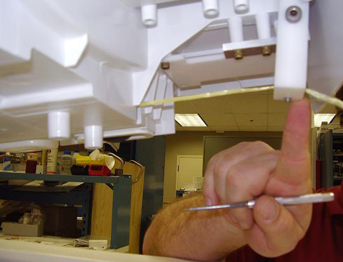
Finalization
Finalization
Make sure that the cradle attaches to the LPCA, and the latch mechanism operates correctly.