
- Discovery MR750 3.0T System Service Methods
- 5690009-2EN Revision 4
- 00000018WIA3008C030GYZ
- id_123747031.5
- Nov 27, 2019 10:21:28 AM
Body Coil Air Flow Functional Check
Prerequisites
| Required persons | Preliminary requirements | Procedure | Finalization |
|---|---|---|---|
| 1 | - | 10-15 minutes for Section 4.1; 60 minutes including Sections 4.1 and 4.2 | - |
| ||||
| Condition | Reference | Effectivity |
|---|---|---|
|
System software must be booted. | - | - |
About this task
Overview
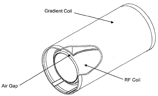
This test checks the functionality of the body coil air blower system, which cools the patient bore wall surfaces by forcing air between the gradient coil and the RF coil Figure 1. Air enters the RF coil through two rear air ports; therefore, the rear of the RF coil needs to have an air tight seal (foam and gasket) in order to maintain a sufficient pressure head to force air to flow. This helps to transfer heat away from the bore wall with convection. If there is not air tight seal (foam and gasket) in the rear of the RF coil, there will not be enough pressure to force air through the space between the gradient and RF coils.
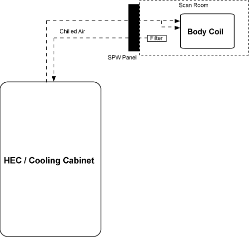
The system currently has a configuration according to the block diagram shown in Figure 2. Air is pulled out of the magnet room and travels through the penetration wall and into the heat exchanger cabinet (HEC). This air is then cooled and sent back through the penetration wall and into the magnet room. This cooled air then travels from the penetration wall, splits into two air hoses, and into the back of the RF coil through tubing in the body coil. At the front of the magnet are two air sensors that capture an average airflow measurement and relay the information back to the HEC display. This airflow requires a measurement of greater than 500 feet per minute (fpm) during scanning operations. If the airflow measurement is less than 500 fpm, refer to Troubleshooting Body Coil Air Flow.
Checking Body Coil Air Flow
About this task
This procedure consists of taking readings from the HEC display on the heat exchanger cabinet and determining if an error is occurring with the air flow system.
Procedure
- Go to the heat exchanger cabinet (HEC) and view the display.
- Select the following buttons from the main menu display in order
to view the air flow set point and feedback readings:
- Note:Monitor (F3)
Select ESC multiple times to return to the main menu display.
- Blower (F4)
- Confirm that the air flow set point corresponds to a measurement equal to or greater than 550 fpm.
- Confirm that the air flow feedback corresponds to a measurement
greater than 500 fpm.
- If the feedback is lower than 500 fpm, refer to Troubleshooting Body Coil Air Flow to troubleshoot the body coil air flow.
- If the feedback is greater than or equal to the Normal mode set point, the system is functioning properly.
Troubleshooting Body Coil Air Flow
About this task
The air flow fpm should always be greater than 500 fpm. In situations where the fpm falls under 500 fpm, follow the checklist for troubleshooting below. After each checklist task, look at the HEC control panel to see if the air flow fpm is 500 fpm or greater.
Procedure
- Note:Verify that the farthest right blower variable frequency drive (VFD) display is reading 60 Hz.
If the air flow fpm is between 450 fpm and 500 fpm, the system will be able to complete a scan, but unable to initiate a scan. If the air flow falls under 450 fpm, the scan control system will automatically shut down.
Figure 3. VFD Blower Display in HEC 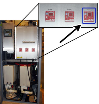
- Remove the right front cover to do the following (see Front Cover Removal and Installation):
-
Check the orientation of the sensors. The sensor head should be in the center of the cutout and the orientation of the sensor head should be perpendicular to air flow (i.e., the flat surface of the sensor should be perpendicular to air flow).
-
Check that there is no cable routing obstructing the air flow.
Figure 4. Front End Bell Sensors 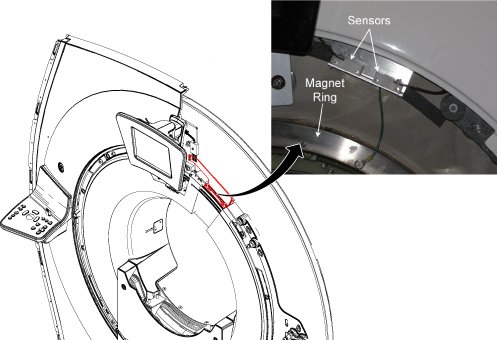
-
Check that the air flow sensors are completely below the edge of the front end bell. The bracket position can be adjusted without removing the front end bell.
Figure 5. Sensor Locations 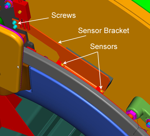
-