
- Discovery MR750 3.0T System Service Methods
- 5690009-2EN Revision 4
- 00000018WHA30A3C6GYZ
- id_20018518.3
- Nov 30, 2021 1:53:39 PM
Doing system gain calibration (DV27 or later)
Prerequisites
| Personnel requirements | |||
|---|---|---|---|
| Required persons | Preliminary requirements | Procedure | Finalization |
| 1 | 5 minutes | 10 minutes | 2 minutes |
| Tools and test equipment | |||
|---|---|---|---|
| Item | Quantity | Part number | Manufacturer |
| Body TLT Sphere for 3.0T (Pink Solution) | 1 | 2360025 | - |
| Body TLT Loader for 3.0T | 1 | 2360037 | - |
| Head TLT Loader for 3.0T | 1 | 2360031 | - |
| Head TLT sphere for 3.0T (pink solution) | 1 | 2359877 |
- |
| 3.0T split-top head coil | 1 | 5182872 | - |
| GEM coil phantom foam support | 1 | 5404900 | - |
About this task
| Notice | |
|---|---|
System gain calibration determines the body and T/R (transmit/receive) head recon scale factors that will achieve a known level of image intensity when you use the body and T/R head coils with a known phantom solution and protocol. The goal is that when the same solution or tissue is scanned in the standard body and T/R head coils with the same protocol, those tissues will have approximately the same image intensity level on a given system and between systems of like type.
This calibration accounts for differences in body receive coil and T/R head coil sensitivity, preamp gains, cable loss, receiver gain, and other factors. The calibration must be done on the body at least once to calibrate those paths.
Procedure
- Position the head sphere in the head loader and fasten the strap. Position the head loader on top of the head loader positioner in the head coil so the loader's black center line lies directly below the head coil's superior/inferior center marker.Note: 3.0T spheres are pink. 1.5T spheres are light green.
Figure 1. Positioning head sphere loader 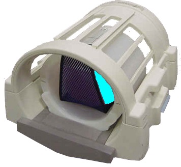
Figure 2. Landmark head sphere 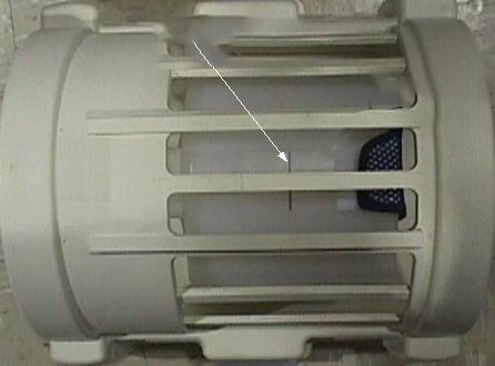
- Select the Start button.
Figure 3. Run system gain calibration (example) 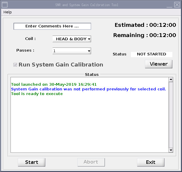
Result
The calibration starts. After it is complete, the tool window shows that the calibration is completed. If adjustments are necessary, the system asks, Do you want to save the recon scale factor?