
- Discovery MR750 3.0T System Service Methods
- 5690009-2EN Revision 4
- 00000018WIA3061B030GYZ
- id_123736581.12
- Oct 11, 2021 3:47:41 PM
1-Wire Network Troubleshooting
Theory of Operation
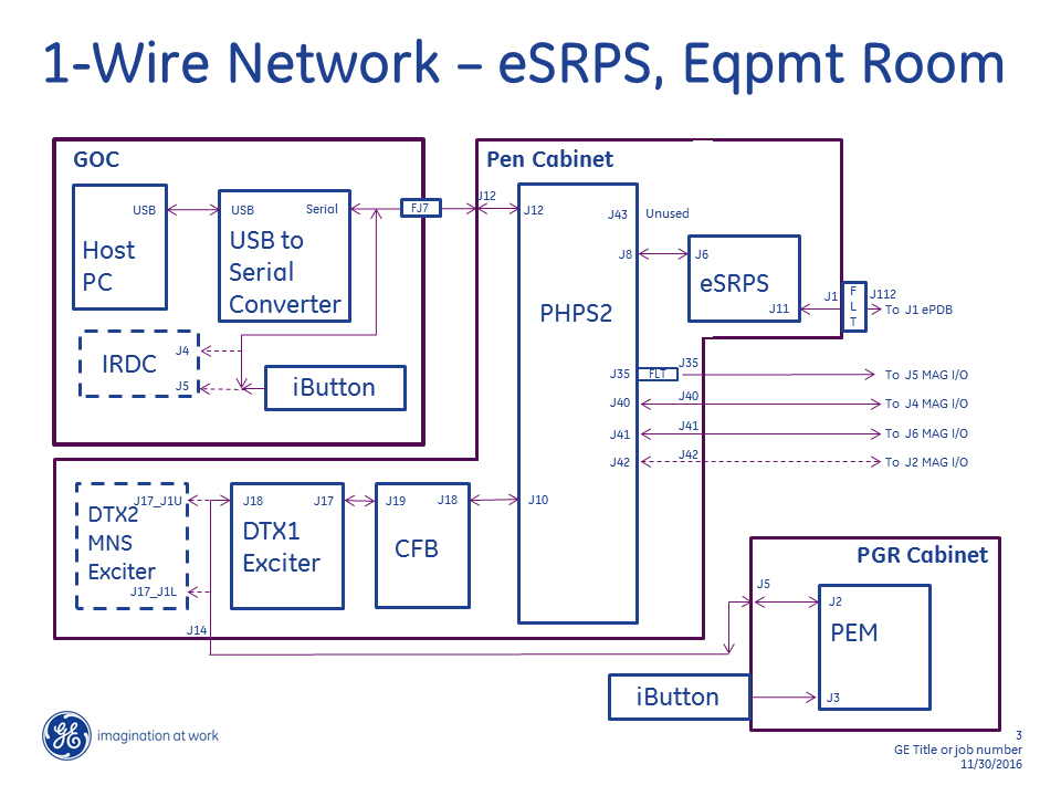
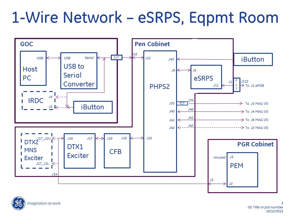
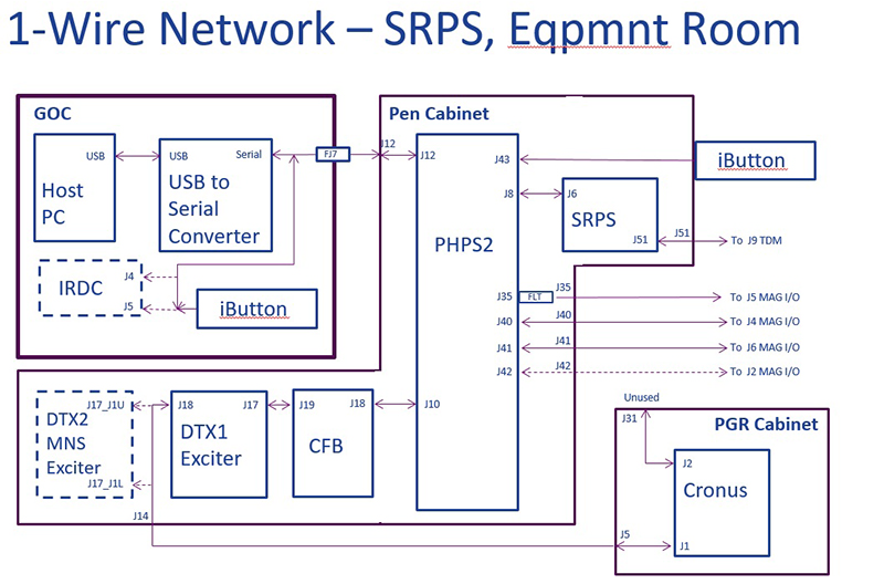
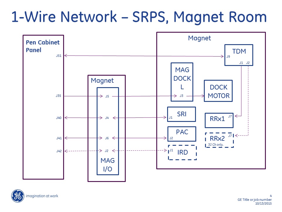
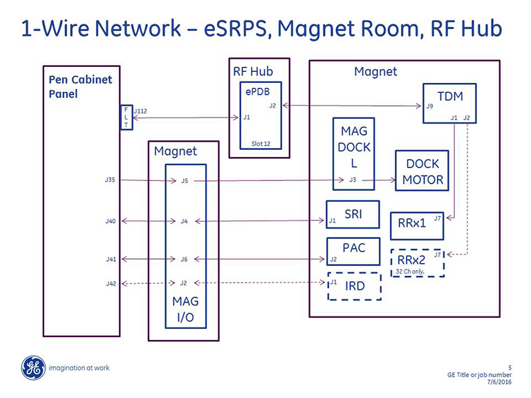
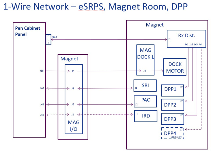
The 1-wire network provides a secondary means for the system to receive hardware and status information from 1-wire capable components. Some components can be “reset” over the 1-wire network. Table 1 below provides a listing of all 1-wire capable components.
| Component | Component Location | Connection at PHPS2 | 1-Wire Reset? (Y/N) |
| Cronus - GMC Board | PGR Cabinet, Cronus | J10 | Y |
| NB DTX1 Exciter | Pen Cabinet | J10 | Y |
| BB (MNS) DTX2 Exciter | Pen Cabinet | J10 | Y |
| CFB | Pen Cabinet | J10 | Y |
| PHPS2 | Pen Cabinet | J12 | N |
| SRPS | Pen Cabinet | J8 | Y |
| eSRPS | Pen Cabinet | J8 | Y |
| In-Room Display Controller Module | GOC | J12 | N |
| PAC | Magnet | J41 | N |
| SRI | Magnet | J40 | Y |
| In-Room Display Monitor | Magnet | J42 | N |
| TDM | Magnet | J8 | N |
| PEM Module | PGR Cabinet | J10 | Y |
| iButton | GOC | J12 | N |
| iButton | PGR or Pen Cabinet | J12 | N |
| RRx1 (supported by TDM) | Magnet | J8 | N |
| RRx2 (supported by TDM) | Magnet | J8 | N |
| 1-Wire lines present but not used at Dock | Magnet, Dock | Thru sub-D filter at J35 | N |
| Rx Distribution Module | Magnet | J8 | N |
The PHPS2 module is the central hub of 1-wire communication. All 1-Wire communication paths ultimately connect at the PHPS2. The PHPS2 must be connected and powered on to permit any communication on the 1-Wire network. The PHPS2 is responsible for receiving 1-wire data from all the 1-wire devices and then converting this data to RS422 serial. This serial data is then forwarded from the PHPS2 to the Host PC through the Serial-to-USB converter box located in the rear of the GOC. The direction of information travel is reversed for any data the Host PC forwards to any 1-wire device on the network; that is, the Host PC forwards information to PHPS2, then PHPS2 forwards to 1-wire device.
Troubleshooting
In order to troubleshoot a problem on the 1-Wire Network, the PHPS must be powered on and connected to the Host PC through the USB-to-Serial Converter and Host PC applications software must be running.
-
Use the 1-Wire Network Diagnostic shown below to test the components on the network.
-
Select optional ‘Force 1-Wire Reset’ only when it is desired to force a component to reset due to unresponsiveness, etc.
-
Selecting ‘Force 1-Wire Reset’ adds 3 minutes to the test execution time and resets the following devices on the 1-Wire Network: DTX1 Exciter, DTX2 Exciter, CFB, SRI, GMC Board, SRPS, and PEM.
-
Select this only if necessary.
-
-
Select optional ‘Display Extended 1-Wire Information’ only if components are reporting failures and it is desired to see details not normally displayed.
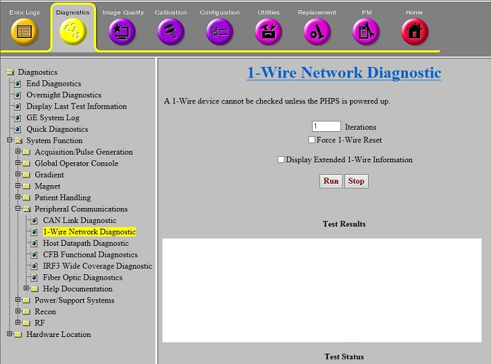
The four possible normal output listings are provided in latter sections of this document. See Table 2 below to determine correct output listing for existing hardware and selected diagnostic options. Any components not communicating are displayed in red font.
| Hardware: | “Display Extended 1-Wire Information” selected? | See Output listing in: |
| SRPS and XGA | N | Table 4 |
| SRPS and XGA | Y | Table 5 |
| eSRPS and XG2 | N | Table 6 |
| eSRPS and XG2 | Y | Table 7 |
Use the Troubleshooting Matrix in Table 3 to diagnose a failing 1-Wire component.
Remove PHPS2 and SRPS power before removing or connecting any cable.
After a power cycle, it is not necessary to perform a TPS Reset before executing 1-Wire Diagnostic. After the power cycle, some item sub-functions may report failure until next successful TPS Reset. The item can be detected and diagnosed with these sub-functions failing.
| Symptom | Action |
| Single item not reported, remaining items reported. | See Figure 2, Figure 3, Figure 5, and Figure 6.
|
| Some items reported but multiple items not reported. | See Figure 2, Figure 3, Figure 5, and Figure 6. The network is a serial configuration.
|
| All items not reported. | See Figure 2 and Figure 3.
|
Remove SRPS power before disconnecting or connecting J51 or J9 cable.
Remove eSRPS power before disconnecting or connecting any cables.
Remove eSRPS power before disconnecting or connecting any cables.
| Device Detected/Not Detected | Notes |
|---|---|
| PHPS Board ID Detected | |
| CFB Cable Present | |
| Table Power Supply OK | |
| CFB Board ID Detected | |
| CFB Digital Power OK | |
| CFB CAN Power OK | |
| CFB I/O Detected | |
| CFB CAN Node: 3 | |
| NB Exc Board ID Detected | |
| Exciter Digital Power OK | |
| Exciter Fiber Optic Signal Presence | |
| NB Exc I/O Detected | |
| Exciter 80MHz Clock OK | |
| Exciter Fiber Optic Link Up | |
| Clk Ref Board ID Detected | |
| Exciter Clock Ref 12V Present | |
| Exciter Clock Ref 80MHz Detected | |
| XGD GMC Board ID Detected | |
| XGD GMC Power OK | |
| XGD GMC Ethernet and DVMR Link OK | If DVMR Link or Ethernet “Not Ok”, successful TPS Reset required to recover |
| XGD GMC Board I/O Detected | |
| SRI Board ID Detected | |
| SRI Digital Power OK | |
| SRI Digital Power Enabled | |
| SRI I/O Detected | |
| SRI CAN Fiber Optic Loopback Disabled | |
| RIB Board ID Detected | |
| IRD Board ID Detected | In Room Display Monitor |
| IRD Power OK | In Room Display Monitor |
| IRD I/O Detected | In Room Display Monitor |
| IRD Power OK | In Room Display Monitor |
| IRD USB1 Detected | In Room Display Monitor |
| IRD USB2 Detected | In Room Display Monitor |
| IRD FPGA Initialized | In Room Display Monitor |
| IRD Sync Detected | In Room Display Monitor |
| SRPS PDB Board ID Detected | |
| SRPS HS OT Not Faulted | |
| SRPS Fan Run Not Faulted | |
| SRPS Exc Board ID Detected | |
| SRPS Exc I/O Detected | |
| SRPS Main AC Input Voltage OK | |
| SRPS +5.3V Under Voltage Sense OK | |
| SRPS +5.3V Over Voltage Sense OK | |
| SRPS Exciter Over Voltage Not Faulted | |
| SRPS Exciter Over Current Not Faulted | |
| SRPS HUB I/O Detected | |
| SRPS Cable Detected +8.5V | |
| SRPS Hub +8.5V Under Voltage Sense OK | |
| SRPS Hub +8.5V Over Voltage Sense OK | |
| SRPS Hub Over Voltage Not Faulted | |
| SRPS Hub Over Current Not Faulted | |
| SRPS TCB I/O Detected | |
| SRPS +3.16V Under Voltage Sense OK | |
| SRPS +3.16V Over Voltage Sense OK | |
| SRPS +5.05V Under Voltage Sense OK | |
| SRPS +5.05V Over Voltage Sense OK | |
| SRPS TDM Over Voltage Not Faulted | |
| SRPS TDM Over Current Not Faulted | |
| SRPS Cable Detect I/O Detected | |
| SRPS Exciter Cable Detected | |
| SRPS RF Hub Cables Detected | |
| SRPS TDM Cables Detected | |
| SRPS Severe Fault Not Detected | |
| SRPS TDM I/O Detected | |
| TDM Board ID Detected | |
| TDM I/O Detected | |
| SRPS TDM Input Power OK | |
| SRPS TDM Internal 3.3V Power OK | |
| SRPS TDM Clock Input Present | |
| SRPS TDM Clock Output Present | |
| SRPS TDM Loop Antenna Present | |
| TDM RRx I/O Detected | |
| RRx 1 Present | |
| RRx 2 Present | 32ch system only |
| Display I/F Box Board ID Detected | In Room Display Module inside GOC |
| Display I/F Box I/O Detected | In Room Display Module inside GOC |
| Display Interface Power OK | In Room Display Module inside GOC |
| Display Interface DVI Connected | In Room Display Module inside GOC |
| Display Interface Video Timing OK | In Room Display Module inside GOC |
| Display Interface FPGA Done | In Room Display Module inside GOC |
| Display Interface USB Power OK | In Room Display Module inside GOC; “Not Ok”, if monitor power off |
| Display Interface USB Link OK | In Room Display Module inside GOC; “Not Ok”, if monitor power off |
| Display Interface Fiber OK | In Room Display Module inside GOC |
| GOC Temp Detected | Located at rear of GOC |
| Equip Room Temp Detected | Located at top of PGR or Pen Cabinet |
| Device Detected/Not Detected | Notes |
|---|---|
| PHPS Board ID Detected | |
| CFB Cable Present | |
| Table Power Supply OK | |
| Serial Number: EE0000090B231B1C | Characters vary by component. |
| Board Identifier: 1PHPS2HDV045167111 | |
| Acronym: PHPS2HDV045167111 | Characters vary by component. |
| ID: 045167111 | Characters vary by component. |
| Part Number: 5167111 | Characters vary by component. |
| Barcode: HL6HP0 | Characters vary by component. |
| Assembly Version: 105 | Characters vary by component. |
| Fab Revision: 5 | Characters vary by component. |
| Lot Code: 26534 | Characters vary by component. |
| Assembly Date: 14SEP2011 | Characters vary by component. |
| Firmware 1 Revision: NOT_APPL | |
| Firmware 2 Revision: NOT_APPL | |
| Hardware 1 Revision: NOT_APPL | |
| Hardware 2 Revision: NOT_APPL | |
| Additional Information: NONE | |
| CFB Board ID Detected | |
| CFB Digital Power OK | |
| CFB CAN Power OK | |
| Serial Number: 6D000009A9341F1C | Characters vary by component. |
| Board Identifier: 1 | Characters vary by component. |
| Acronym: CFBHDv | Characters vary by component. |
| ID: 01 | Characters vary by component. |
| Part Number: 5250048 | Characters vary by component. |
| Barcode: AJEDNT | Characters vary by component. |
| Assembly Version: H | Characters vary by component. |
| Fab Revision: 4 | Characters vary by component. |
| Lot Code: NONE | Characters vary by component. |
| Assembly Date: 04NOV2011 NOT_APPL | Characters vary by component. |
| Firmware 1 Revision: NOT_APPL | |
| Firmware 2 Revision: NOT_APPL | |
| Hardware 1 Revision: NOT_APPL | |
| Hardware 2 Revision: NOT_APPL | |
| Additional Information: NONE | |
| CFB I/O Detected | |
| CFB CAN Node: 3 | |
| CFB 1-Wire Remote Reset: 1 | |
| Spare[3] = 0 | |
| Spare[4] = 0 | |
| Spare[5] = 0 | |
| Spare[6] = 0 | |
| Spare[7] = 0 | |
| NB Exc Board ID Detected | |
| Exciter Digital Power OK | |
| Exciter Fiber Optic Signal Presence | |
| Serial Number: E800000422AB7F1C | Characters vary by component. |
| Board Identifier: 1NBEXCHDv035250090 | Characters vary by component. |
| Acronym: NBEXCHDv035250090 | Characters vary by component. |
| ID: 035250090 | Characters vary by component. |
| Part Number: 5250090 | Characters vary by component. |
| Barcode: AL58DN | Characters vary by component. |
| Assembly Version: E | Characters vary by component. |
| Fab Revision: 5 | Characters vary by component. |
| Lot Code: WO#126767313NOV2009 | Characters vary by component. |
| Assembly Date: 13NOV2009 | |
| Firmware 1 Revision: NOT_APPL | |
| Firmware 2 Revision: NOT_APPL | |
| Hardware 1 Revision: NOT_APPL | |
| Hardware 2 Revision: NOT_APPL | |
| Additional Information: NONE | |
| NB Exc I/O Detected | |
| Exciter 80MHz Clock OK | |
| Exciter Fiber Optic Link Up | |
| Exciter Board 1-Wire Reset: 1 | |
| Spare[3] = 0 | |
| Spare[4] = 0 | |
| Spare[5] = 0 | |
| Spare[6] = 0 | |
| Spare[7] = 0 | |
| Clk Ref Board ID Detected | |
| Exciter Clock Ref 12V Present | |
| Exciter Clock Ref 80MHz Detected | |
| Serial Number: F200000422E27F1C | Characters vary by component. |
| Board Identifier: 1CLKREF | |
| Acronym: CLKREF | |
| ID: 115250092 | Characters vary by component. |
| Part Number: 5250092 | Characters vary by component. |
| Barcode: AL574N | Characters vary by component. |
| Assembly Version: C | Characters vary by component. |
| Fab Revision: 3 | Characters vary by component. |
| Lot Code: WO#126767410NOV2009 | Characters vary by component. |
| Assembly Date: 10NOV2009 | Characters vary by component. |
| Firmware 1 Revision: NOT_APPL | |
| Firmware 2 Revision: NOT_APPL | |
| Hardware 1 Revision: NOT_APPL | |
| Hardware 2 Revision: NOT_APPL | |
| Additional Information: NONE | |
| XGD GMC Board ID Detected | |
| XGD GMC Power OK | |
| XGD GMC Ethernet and DVMR Link OK | If DVMR Link or Ethernet “Not Ok”, successful TPS Reset required to recover. |
| Serial Number: EB0000098F267F1C | Characters vary by component. |
| Board Identifier: 1XGD_GMC | |
| Acronym: XGD_GMC | |
| ID: 085250128 | Characters vary by component. |
| Part Number: 5250128 | Characters vary by component. |
| Barcode: AJENTF | Characters vary by component. |
| Assembly Version: E | Characters vary by component. |
| Fab Revision: 03 | Characters vary by component. |
| Lot Code: NOT_APPL | |
| Assembly Date: 19DEC2011 | Characters vary by component. |
| Firmware 1 Revision: NOT_APPL | |
| Firmware 2 Revision: NOT_APPL | |
| Hardware 1 Revision: NOT_APPL | |
| Hardware 2 Revision: NOT_APPL | |
| Additional Information: NONE | |
| XGD GMC Board I/O Detected | |
| XGD GMC Board 1-Wire Reset: 1 | |
| Spare[2] = 1 | |
| Spare[3] = 1 | |
| Spare[4] = 1 | |
| Spare[5] = 1 | |
| Spare[6] = 1 | |
| Spare[7] = 1 | |
| SRI Board ID Detected | |
| SRI Digital Power OK | |
| SRI Digital Power Enabled | |
| Serial Number: A400000389821B1C | Characters vary by component. |
| Board Identifier: 1 | Characters vary by component. |
| Acronym: SRI4HDv | |
| ID: 04 | Characters vary by component. |
| Part Number: 5250108 | Characters vary by component. |
| Barcode: AJ7M9L | Characters vary by component. |
| Assembly Version: F | Characters vary by component. |
| Fab Revision: 3 | Characters vary by component. |
| Lot Code: NONE | |
| Assembly Date: 12FEB2009 NOT_APPL | Characters vary by component. |
| Firmware 1 Revision: NOT_APPL | |
| Firmware 2 Revision: NOT_APPL | |
| Hardware 1 Revision: NOT_APPL | |
| Hardware 2 Revision: NOT_APPL | |
| Additional Information: NONE | |
| SRI I/O Detected | |
| SRI CAN Fiber Optic Loopback Disabled | |
| SRI 1-Wire Reset: 1 | |
| Spare[2] = 0 | |
| Spare[3] = 0 | |
| Spare[4] = 0 | |
| Spare[5] = 0 | |
| Spare[6] = 0 | |
| Spare[7] = 0 | |
| RIB Board ID Detected | |
| Spare[0] = 0 | |
| Spare[1] = 0 | |
| Serial Number: 920000037AFC0B1C | Characters vary by component. |
| Board Identifier: 1 | Characters vary by component. |
| Acronym: RIB3_HDv | |
| ID: 07 | Characters vary by component. |
| Part Number: 6250014 | Characters vary by component. |
| Barcode: AJ7NB7 | Characters vary by component. |
| Assembly Version: B | Characters vary by component. |
| Fab Revision: 2 | Characters vary by component. |
| Lot Code: NONE | |
| Assembly Date: 12FEB2009 | Characters vary by component. |
| Firmware 1 Revision: NOT_APPL | |
| Firmware 2 Revision: NOT_APPL | |
| Hardware 1 Revision: NOT_APPL | |
| Hardware 2 Revision: NOT_APPL | |
| Additional Information: NONE | |
| IRD Board ID Detected | In Room Display Monitor. |
| IRD Power OK | In Room Display Monitor. |
| IRD Board ID Input 1 is Valid | In Room Display Monitor. |
| Serial Number: F3000000EC8C031C | In Room Display Monitor; vary by component. |
| Board Identifier: 1 | In Room Display Monitor; vary by component. |
| Acronym: IRMHDv | In Room Display Monitor. |
| ID: 06 | In Room Display Monitor; vary by component. |
| Part Number: 5133768 | In Room Display Monitor; vary by component. |
| Barcode: K189012429901 | In Room Display Monitor; vary by component. |
| Assembly Version: 01 | In Room Display Monitor; vary by component. |
| Fab Revision: | In Room Display Monitor; vary by component. |
| Lot Code: | In Room Display Monitor; vary by component. |
| Assembly Date: 12Mar2008 | In Room Display Monitor; vary by component. |
| Firmware 1 Revision: NOT_APPL | In Room Display Monitor. |
| Firmware 2 Revision: NOT_APPL | In Room Display Monitor. |
| Hardware 1 Revision: NOT_APPL | In Room Display Monitor. |
| Hardware 2 Revision: NOT_APPL | In Room Display Monitor. |
| Additional Information: NONE | In Room Display Monitor. |
| IRD I/O Detected | In Room Display Monitor. |
| IRD Power OK | In Room Display Monitor. |
| IRD USB1 Detected | In Room Display Monitor. |
| IRD USB2 Detected | In Room Display Monitor. |
| IRD FPGA Initialized | In Room Display Monitor. |
| IRD Sync Detected | In Room Display Monitor. |
| Spare[5] = 1 | In Room Display Monitor. |
| Spare[6] = 1 | In Room Display Monitor. |
| Spare[7] = 1 | In Room Display Monitor. |
| SRPS PDB Board ID Detected | |
| SRPS HS OT Not Faulted | |
| SRPS Fan Run Not Faulted | |
| Serial Number: CA000009A1BF171C | Characters vary by component. |
| Board Identifier: 1 | Characters vary by component. |
| Acronym: SRPS_PDB | |
| ID: 12 | Characters vary by component. |
| Part Number: 5231801 | |
| Barcode: AJE5LJ | Characters vary by component. |
| Characters vary by component. | |
| Fab Revision: NOT_ | Characters vary by component. |
| Lot Code: | Characters vary by component. |
| Assembly Date: | Characters vary by component. |
| Firmware 1 Revision: NOT_APPL | |
| Firmware 2 Revision: NOT_APPL | |
| Hardware 1 Revision: NOT_APPL | |
| Hardware 2 Revision: NOT_APPL | |
| Additional Information: NONE | |
| SRPS Exc Board ID Detected | |
| SRPS Exciter Board ID Input 0 is Valid | |
| SRPS Exciter Board ID Input 1 is Valid | |
| Serial Number: 14000009AB5B1B1C | Characters vary by component. |
| Board Identifier: 1 | Characters vary by component. |
| Acronym: SRPS_FRU | |
| ID: 13 | Characters vary by component. |
| Part Number: 5300128 | Characters vary by component. |
| Barcode: AJE8N3 | Characters vary by component. |
| Assembly Version: F | Characters vary by component. |
| Fab Revision: 4 | Characters vary by component. |
| Lot Code: | Characters vary by component. |
| Assembly Date: | Characters vary by component. |
| Firmware 1 Revision: NOT_APPL | |
| Firmware 2 Revision: NOT_APPL | |
| Hardware 1 Revision: NOT_APPL | |
| Hardware 2 Revision: NOT_APPL | |
| Additional Information: NONE | |
| SRPS Exc I/O Detected | |
| SRPS Exciter ID: 0 | |
| SRPS Main AC Input Voltage OK | |
| SRPS +5.3V Under Voltage Sense OK | |
| SRPS +5.3V Over Voltage Sense OK | |
| SRPS Exciter Over Voltage Not Faulted | |
| SRPS Exciter Over Current Not Faulted | |
| SRPS HUB I/O Detected | |
| SRPS Hub ID: 1 | |
| SRPS Cable Detected +8.5V | |
| SRPS Voltage Sense 1-Wire Reset: 1 | |
| SRPS Hub +8.5V Under Voltage Sense OK | |
| SRPS Hub +8.5V Over Voltage Sense OK | |
| SRPS Hub Over Voltage Not Faulted | |
| SRPS Hub Over Current Not Faulted | |
| SRPS TCB I/O Detected | |
| SRPS TCB ID: 2 | |
| SRPS +3.16V Under Voltage Sense OK | |
| SRPS +3.16V Over Voltage Sense OK | |
| SRPS +5.05V Under Voltage Sense OK | |
| SRPS +5.05V Over Voltage Sense OK | |
| SRPS TDM Over Voltage Not Faulted | |
| SRPS TDM Over Current Not Faulted | |
| SRPS Cable Detect I/O Detected | |
| SRPS Cable Detect ID: 3 | |
| SRPS Fault 1-Wire Reset: 1 | |
| SRPS Exciter Cable Detected | |
| SRPS RF Hub Cables Detected | |
| SRPS TDM Cables Detected | |
| SRPS Severe Fault Not Detected | |
| SRPS TDM I/O Detected | |
| SRPS TDM Input 0 is Valid | |
| SRPS TDM Input 1 is Valid | |
| SRPS TDM Input 2 is Valid | |
| SRPS TDM Input 3 is Valid | |
| Spare[4] = 0 | |
| Spare[5] = 0 | |
| Spare[6] = 0 | |
| Spare[7] = 0 | |
| TDM Board ID Detected | |
| Spare[0] = 0 | |
| Spare[1] = 0 | |
| Serial Number: BF000003EE2A7F1C | Characters vary by component. |
| Board Identifier: 1TDM_HDV | |
| Acronym: TDM_HDV | |
| ID: 155250164 | Characters vary by component. |
| Part Number: 5250164 | Characters vary by component. |
| Barcode: AL3Z80 | Characters vary by component. |
| Assembly Version: G | Characters vary by component. |
| Fab Revision: 4 | Characters vary by component. |
| Lot Code: WO#966633 | Characters vary by component. |
| Assembly Date: 16FEB2009 | Characters vary by component. |
| Firmware 1 Revision: NOT_APPL | |
| Firmware 2 Revision: NOT_APPL | |
| Hardware 1 Revision: NOT_APPL | |
| Hardware 2 Revision: NOT_APPL | |
| Additional Information: NONE | |
| TDM I/O Detected | |
| SRPS TDM Input Power OK | |
| SRPS TDM Internal 3.3V Power OK | |
| SRPS TDM Clock Input Present | |
| SRPS TDM Clock Output Present | |
| SRPS TDM Loop Antenna Present | |
| TDM Revision = 0 | |
| TDM RRx I/O Detected | |
| RRx 1 Present | |
| RRx 2 Present | |
| Display I/F Box Board ID Detected | In Room Display Module inside GOC. |
| Display I/F Box Board ID Input 0 is Valid | In Room Display Module inside GOC. |
| Display I/F Box Board ID Input 1 is Valid | In Room Display Module inside GOC. |
| Serial Number: E60000015BAB031C | In Room Display Module inside GOC vary by component. |
| Board Identifier: 1 | In Room Display Module inside GOC vary by component. |
| Acronym: DIFOCHDv 14 5133768 | In Room Display Module inside GOC. |
| ID: 14 5133768 | In Room Display Module inside GOC vary by component. |
| Part Number: 5133768 | In Room Display Module inside GOC. |
| Barcode: | In Room Display Module inside GOC vary by component. |
| Assembly Version: | In Room Display Module inside GOC vary by component. |
| Fab Revision: | In Room Display Module inside GOC vary by component. |
| Lot Code: | In Room Display Module inside GOC vary by component. |
| Assembly Date: | In Room Display Module inside GOC vary by component. |
| Firmware 1 Revision: NOT_APPL | In Room Display Module inside GOC. |
| Firmware 2 Revision: NOT_APPL | In Room Display Module inside GOC. |
| Hardware 1 Revision: NOT_APPL | In Room Display Module inside GOC. |
| Hardware 2 Revision: NOT_APPL | In Room Display Module inside GOC. |
| Additional Information: NONE | In Room Display Module inside GOC. |
| Display I/F Box I/O Detected | In Room Display Module inside GOC. |
| Display Interface Power OK | In Room Display Module inside GOC. |
| Display Interface DVI Connected | In Room Display Module inside GOC. |
| Display Interface Video Timing OK | In Room Display Module inside GOC. |
| Display Interface FPGA Done | In Room Display Module inside GOC. |
| Unused[4] = 1 | In Room Display Module inside GOC. |
| Display Interface USB Power OK | In Room Display Module inside GOC; “Not Ok”, if monitor power off. |
| Display Interface USB Link OK | In Room Display Module inside GOC; “Not Ok”, if monitor power off. |
| Display Interface Fiber OK | Note: In Room Display Module inside GOC. |
| GOC Temp Detected | Located at rear of GOC |
| Equip Room Temp Detected | Located at top of PGR or Pen Cabinet |
| Device Detected/Not Detected | Notes |
|---|---|
| PHPS Board ID Detected | |
| CFB Cable Present | |
| Table Power Supply OK | |
| CFB Board ID Detected | |
| CFB Digital Power OK | |
| CFB CAN Power OK | |
| CFB I/O Detected | |
| CFB CAN Node: 3 | |
| NB Exc Board ID Detected | |
| Exciter Digital Power OK | |
| Exciter Fiber Optic Signal Presence | |
| NB Exc I/O Detected | |
| Exciter 80MHz Clock OK | |
| Exciter Fiber Optic Link Up | |
| Clk Ref Board ID Detected | |
| Exciter Clock Ref 12V Present | |
| Exciter Clock Ref 80MHz Detected | |
| SRI Board ID Detected | |
| SRI Digital Power OK | |
| SRI Digital Power Enabled | |
| SRI I/O Detected | |
| SRI CAN Fiber Optic Loopback Disabled | |
| RIB Board ID Detected | |
| TDM Board ID Detected | |
| TDM I/O Detected | |
| SRPS TDM Input Power OK | |
| SRPS TDM Internal 3.3V Power OK | |
| SRPS TDM Clock Input Present | |
| SRPS TDM Clock Output Present | |
| SRPS TDM Loop Antenna Present | |
| TDM RRx I/O Detected | |
| RRx 1 Present | |
| RRx 2 Present | |
| Display I/F Box Board ID Detected | In Room Display Module inside GOC. |
| Display I/F Box I/O Detected | In Room Display Module inside GOC. |
| Display Interface Power OK | In Room Display Module inside GOC. |
| Display Interface DVI Connected | In Room Display Module inside GOC. |
| Display Interface Video Timing OK | In Room Display Module inside GOC. |
| Display Interface FPGA Done | In Room Display Module inside GOC. |
| Display Interface USB Power OK | In Room Display Module inside GOC. |
| Display Interface USB Link OK | In Room Display Module inside GOC; “Not Ok”, if monitor power off |
| Display Interface Fiber OK | In Room Display Module inside GOC; “Not Ok”, if monitor power off |
| GOC Temp Detected | Located at rear of GOC. |
| Equip Room Temp Detected | Located at top of Pen Cabinet. |
| BB Exc Board ID Detected | |
| MNS Exciter Digital Power OK | |
| MNS Exciter Fiber Optic Signal Presence | |
| BB Exc I/O Detected | |
| MNS Exciter 80MHz Clock OK | |
| MNS Exciter Fiber Optic Link Up | |
| PEM Board ID Detected | |
| PEM Power OK | |
| PEM FPGA OK | |
| PEM Board I/O Detected | |
| PEM Software OK | |
| PEM 48V OK | |
| PAC Board ID Detected | |
| PAC PM Fault I/O Detected | |
| PAC Power Monitor 1.8V Power OK | |
| PAC Power Monitor 3.3V Power OK | |
| PAC Power Monitor -5V Power OK | |
| PAC Power Monitor 5V Power OK | |
| PAC Power Monitor 12V Power OK | |
| PAC Power Monitor -12V Power OK | |
| PAC FPGA I/O Detected | |
| PAC FPGA Config Done | |
| PAC FPGA Init Done | |
| PAC Power Monitor 1.2V Power OK | |
| PAC Power Monitor 2.5V Power OK | |
| eSRPS Ctrl Board ID Detected | |
| eSRPS Exc I/O Detected | |
| eSRPS Exciter Over Voltage OK | |
| eSRPS Exciter Under Voltage OK | |
| eSRPS Exciter Over Current OK | |
| eSRPS MNS Exciter Over Voltage OK | |
| eSRPS MNS Exciter Under Voltage OK | |
| eSRPS MNS Exciter Over Current OK | |
| eSRPS Ctrl Board I/O Detected | |
| RF Hub/TDM Power is On | |
| eSRPS AC Input Status OK | |
| eSRPS 12V Voltage OK | |
| eSRPS Control Board Over Temperature OK | |
| eSRPS Control Board Fan OK | |
| eSRPS Power Supply I/O Detected | |
| eSRPS Exciter 22V Over Voltage OK | |
| eSRPS Exciter 22V Under Voltage OK | |
| eSRPS Exciter 22V Power Supply OK | |
| eSRPS RF Hub 22V Over Voltage OK | |
| eSRPS RF Hub 22V Under Voltage OK | |
| eSRPS RF Hub 22V Power Supply OK | |
| eSRPS Cable Detect I/O Detected | |
| eSRPS TDM Cable1 Detected | |
| eSRPS TDM Cable2 Detected | |
| eSRPS Exciter Cables Detected | |
| eSRPS MNS Exciter Cable Detected | |
| eSRPS ePDB Cable Detected | |
| IRD Board ID Detected | In Room Display Monitor. |
| IRD Power OK | In Room Display Monitor. |
| IRD I/O Detected | In Room Display Monitor. |
| IRD Power OK | In Room Display Monitor. |
| IRD USB1 Detected | In Room Display Monitor. |
| IRD USB2 Detected | In Room Display Monitor. |
| IRD FPGA Initialized | In Room Display Monitor. |
| IRD Sync Detected | In Room Display Monitor. |
| Device Detected/Not Detected | Notes |
|---|---|
| PHPS Board ID Detected | |
| CFB Cable Present | |
| Table Power Supply OK | |
| Serial Number: B900000C11F71B1C | Characters vary by component. |
| Board Identifier: 1PHPS2HDV045167111 | Characters vary by component. |
| Acronym: PHPS2HDV045167111 | Characters vary by component. |
| ID: 045167111 | Characters vary by component. |
| Part Number: 5167111 | |
| Barcode: HL01B8VH | Characters vary by component. |
| Assembly Version: 1 | Characters vary by component. |
| Fab Revision: 5 | Characters vary by component. |
| Lot Code: 5221454 | Characters vary by component. |
| Assembly Date: 1FEB2015 | Characters vary by component. |
| Firmware 1 Revision: NOT_APPL | |
| Firmware 2 Revision: NOT_APPL | |
| Hardware 1 Revision: NOT_APPL | |
| Hardware 2 Revision: NOT_APPL | |
| Additional Information: NONE | |
| CFB Board ID Detected | |
| CFB Digital Power OK | |
| CFB CAN Power OK | |
| Serial Number: 01000009F871071C | Characters vary by component. |
| Board Identifier: 1 | Characters vary by component. |
| Acronym: CFBHDv | |
| ID: 01 | Characters vary by component. |
| Part Number: 5250048 | Characters vary by component. |
| Barcode: AVW70K | Characters vary by component. |
| Assembly Version: A | Characters vary by component. |
| Fab Revision: 4 | Characters vary by component. |
| Lot Code: NONE | Characters vary by component. |
| Assembly Date: | Characters vary by component. |
| Firmware 1 Revision: NOT_APPL | |
| Firmware 2 Revision: NOT_APPL | |
| Hardware 1 Revision: NOT_APPL | |
| Hardware 2 Revision: NOT_APPL | |
| Additional Information: NONE | |
| CFB I/O Detected | |
| CFB CAN Node: 3 | |
| CFB 1-Wire Remote Reset: 1 | |
| Spare[3] = 0 | |
| Spare[4] = 0 | |
| Spare[5] = 0 | |
| Spare[6] = 0 | |
| Spare[7] = 0 | |
| NB Exc Board ID Detected | |
| Exciter Digital Power OK | |
| Exciter Fiber Optic Signal Presence | |
| Serial Number: 7200000D131D7F1C | Characters vary by component. |
| Board Identifier: 1NBEXCHDv036300668-2 | Characters vary by component. |
| Acronym: NBEXCHDv036300668-2 | Characters vary by component. |
| ID: 036300668-2 | Characters vary by component. |
| Part Number: 6300668-2 | Characters vary by component. |
| Barcode: ALJVS6 | Characters vary by component. |
| Assembly Version: A | Characters vary by component. |
| Fab Revision: 1 | Characters vary by component. |
| Lot Code: WO#44682585MAY2015 | Characters vary by component. |
| Assembly Date: 5MAY2015 | Characters vary by component. |
| Firmware 1 Revision: NOT_APPL | |
| Firmware 2 Revision: NOT_APPL | |
| Hardware 1 Revision: NOT_APPL | |
| Hardware 2 Revision: NOT_APPL | |
| Additional Information: NONE | |
| NB Exc I/O Detected | |
| Exciter 80MHz Clock OK | |
| Exciter Fiber Optic Link Up | |
| Exciter Board 1-Wire Reset: 1 | |
| Spare[3] = 0 | |
| Spare[4] = 0 | |
| Spare[5] = 0 | |
| Spare[6] = 0 | |
| Spare[7] = 0 | |
| Clk Ref Board ID Detected | |
| Exciter Clock Ref 12V Present | |
| Exciter Clock Ref 80MHz Detected | |
| Serial Number: 1900000CFF297F1C | Characters vary by component. |
| Board Identifier: 1CLKREF | |
| Acronym: CLKREF | |
| ID: 116300646-2 | Characters vary by component. |
| Part Number: 6300646-2 | Characters vary by component. |
| Barcode: ALJXAB | Characters vary by component. |
| Assembly Version: B | Characters vary by component. |
| Fab Revision: 2 | Characters vary by component. |
| Lot Code: WO#441991721APR2015 | Characters vary by component. |
| Assembly Date: 21APR2015 | Characters vary by component. |
| Firmware 1 Revision: NOT_APPL | |
| Firmware 2 Revision: NOT_APPL | |
| Hardware 1 Revision: NOT_APPL | |
| Hardware 2 Revision: NOT_APPL | |
| Additional Information: NONE | |
| SRI Board ID Detected | |
| SRI Digital Power OK | |
| SRI Digital Power Enabled | |
| Serial Number: E000000BF0AC0F1C | Characters vary by component. |
| Board Identifier: 1 | Characters vary by component. |
| Acronym: SRI4HDv | |
| ID: 04 | |
| Part Number: 6250308 | Characters vary by component. |
| Barcode: ALFEXS | Characters vary by component. |
| Assembly Version: C | Characters vary by component. |
| Fab Revision: 3 | Characters vary by component. |
| Lot Code: WO#3719027 | Characters vary by component. |
| Assembly Date: 15MAY2014ONOT_APPL | Characters vary by component. |
| Firmware 1 Revision: NOT_APPL | |
| Firmware 2 Revision: NOT_APPL | |
| Hardware 1 Revision: NOT_APPL | |
| Hardware 2 Revision: NOT_APPL | |
| Additional Information: NONE | |
| SRI I/O Detected | |
| SRI CAN Fiber Optic Loopback Disabled | |
| SRI 1-Wire Reset: 1 | |
| Spare[2] = 0 | |
| Spare[3] = 0 | |
| Spare[4] = 0 | |
| Spare[5] = 0 | |
| Spare[6] = 0 | |
| Spare[7] = 0 | |
| RIB Board ID Detected | |
| Spare[0] = 0 | |
| Spare[1] = 0 | |
| Serial Number: 1A00000BF6A5071C | Characters vary by component. |
| Board Identifier: 1 | Characters vary by component. |
| Acronym: RIB3_HDv | |
| ID: 07 | Characters vary by component. |
| Part Number: 6250014-51 | Characters vary by component. |
| Barcode: ALFH6N | Characters vary by component. |
| Assembly Version: B | Characters vary by component. |
| Fab Revision: 2 | Characters vary by component. |
| Lot Code: WO#3719023 | Characters vary by component. |
| Assembly Date: 15MAY2014NOT_APPL | Characters vary by component. |
| Firmware 1 Revision: NOT_APPL | |
| Firmware 2 Revision: NOT_APPL | |
| Hardware 1 Revision: NOT_APPL | |
| Hardware 2 Revision: NOT_APPL | |
| Additional Information: NONE | |
| TDM Board ID Detected | |
| Spare[0] = 0 | |
| Spare[1] = 0 | |
| Serial Number: 5100000D19947F1C | Characters vary by component. |
| Board Identifier: 1TDM_HDV | |
| Acronym: TDM_HDV | |
| ID: 156250164-2 | Characters vary by component. |
| Part Number: 6250164-2 | Characters vary by component. |
| Barcode: ALJ53S | Characters vary by component. |
| Assembly Version: B | Characters vary by component. |
| Fab Revision: 2 | Characters vary by component. |
| Lot Code: WO#41468147JAN2015 | Characters vary by component. |
| Assembly Date: 7JAN2015 | Characters vary by component. |
| Firmware 1 Revision: NOT_APPL | |
| Firmware 2 Revision: NOT_APPL | |
| Hardware 1 Revision: NOT_APPL | |
| Hardware 2 Revision: NOT_APPL | |
| Additional Information: NONE | |
| TDM I/O Detected | |
| SRPS TDM Input Power OK | |
| SRPS TDM Internal 3.3V Power OK | |
| SRPS TDM Clock Input Present | |
| SRPS TDM Clock Output Present | |
| SRPS TDM Loop Antenna Present | |
| TDM Revision = 1 | |
| TDM RRx I/O Detected | |
| RRx 1 Present | |
| RRx 2 Present | |
| Display I/F Box Board ID Detected | |
| Display I/F Box Board ID Input 0 is Valid | |
| Display I/F Box Board ID Input 1 is Valid | |
| Serial Number: DF000009210D031C | Characters vary by component. |
| Board Identifier: 1DIFOCHDv145133768-2 | Characters vary by component. |
| Acronym: DIFOCHDv145133768-2 | Characters vary by component. |
| ID: 145133768-2 | Characters vary by component. |
| Part Number: 5133768-2 | Characters vary by component. |
| Barcode: K189023066200 | Characters vary by component. |
| Assembly Version: 00 | Characters vary by component. |
| Fab Revision: | Characters vary by component. |
| Lot Code: | Characters vary by component. |
| Assembly Date: 16FEB2011NOT_APPL | Characters vary by component. |
| Firmware 1 Revision: NOT_APPL | |
| Firmware 2 Revision: NOT_APPL | |
| Hardware 1 Revision: NOT_APPL | |
| Hardware 2 Revision: NOT_APPL | |
| Additional Information: NONE | |
| Display I/F Box I/O Detected | In Room Display Module inside GOC. |
| Display Interface Power OK | In Room Display Module inside GOC. |
| Display Interface DVI Connected | In Room Display Module inside GOC. |
| Display Interface Video Timing OK | In Room Display Module inside GOC. |
| Display Interface FPGA Done | In Room Display Module inside GOC. |
| Unused[4] = 1 | In Room Display Module inside GOC. |
| Display Interface USB Power OK | In Room Display Module inside GOC; “Not Ok”, if monitor power off. |
| Display Interface USB Link OK | In Room Display Module inside GOC; “Not Ok”, if monitor power off. |
| Display Interface Fiber OK | In Room Display Module inside GOC. |
| GOC Temp Detected | Located at rear of GOC. |
| Equip Room Temp Detected | Located at top of Pen Cabinet. |
| BB Exc Board ID Detected | |
| MNS Exciter Digital Power OK | |
| MNS Exciter Fiber Optic Signal Presence | |
| Serial Number: 97000009B12A7F1C | Characters vary by component. |
| Board Identifier: 1 | Characters vary by component. |
| Acronym: BBEXCHDv | Characters vary by component. |
| ID: 05 | Characters vary by component. |
| Part Number: 5300118 | Characters vary by component. |
| Barcode: AL8YGC | Characters vary by component. |
| Assembly Version: F | Characters vary by component. |
| Fab Revision: 2 | Characters vary by component. |
| Lot Code: WO#2214514 | Characters vary by component. |
| Assembly Date: 07OCT2011O\NOT_APPL | Characters vary by component. |
| Firmware 1 Revision: NOT_APPL | |
| Firmware 2 Revision: NOT_APPL | |
| Hardware 1 Revision: NOT_APPL | |
| Hardware 2 Revision: NOT_APPL | |
| Additional Information: NONE | |
| BB Exc I/O Detected | |
| MNS Exciter 80MHz Clock OK | |
| MNS Exciter Fiber Optic Link Up | |
| MNS Exciter Board 1-Wire Reset: 1 | |
| Spare[3] = 0 | |
| Spare[4] = 0 | |
| Spare[5] = 0 | |
| Spare[6] = 0 | |
| Spare[7] = 0 | |
| PEM Board ID Detected | |
| PEM Power OK | |
| PEM FPGA OK | |
| Serial Number: 3C00000A70B97F1C | Characters vary by component. |
| Board Identifier: 1 | Characters vary by component. |
| Acronym: PEM | |
| ID: 01 | |
| Part Number: 6250040 | Characters vary by component. |
| Barcode: HM3C7N | Characters vary by component. |
| Assembly Version: | Characters vary by component. |
| Fab Revision: J | Characters vary by component. |
| Lot Code: ASL-NA---- | Characters vary by component. |
| Assembly Date: | Characters vary by component. |
| Firmware 1 Revision: NOT_APPL | |
| Firmware 2 Revision: NOT_APPL | |
| Hardware 1 Revision: NOT_APPL | |
| Hardware 2 Revision: NOT_APPLNONE | |
| Additional Information: NONE | |
| PEM Board I/O Detected | |
| PEM Software OK | |
| PEM 48V OK | |
| PEM Board 1-Wire Reset: 1 | |
| Spare[4] = 1 | |
| Spare[5] = 1 | |
| Spare[6] = 1 | |
| Spare[7] = 1 | |
| PAC Board ID Detected | |
| PAC Board ID Input 0 is Correct | |
| PAC Board ID Input 1 is Correct | |
| Serial Number: 6700000C0B9A001C | Characters vary by component. |
| Board Identifier: 1PACHDv | |
| Acronym: PACHDv | |
| ID: 106300224 | Characters vary by component. |
| Part Number: 6300224 | Characters vary by component. |
| Barcode: HL017TM8 | Characters vary by component. |
| Assembly Version: F | Characters vary by component. |
| Fab Revision: 6 | Characters vary by component. |
| Lot Code: 12345678 | Characters vary by component. |
| Assembly Date: 02DEC2014ONOT_APPL | Characters vary by component. |
| Firmware 1 Revision: NOT_APPL | |
| Firmware 2 Revision: NOT_APPL | |
| Hardware 1 Revision: NOT_APPL | |
| Hardware 2 Revision: NOT_APPL | |
| Additional Information: NONE | |
| PAC PM Fault I/O Detected | |
| PAC Power Monitor ID 0 is Valid | |
| PAC Power Monitor ID 1 is Valid | |
| PAC Power Monitor 1.8V Power OK | |
| PAC Power Monitor 3.3V Power OK | |
| PAC Power Monitor -5V Power OK | |
| PAC Power Monitor 5V Power OK | |
| PAC Power Monitor 12V Power OK | |
| PAC Power Monitor -12V Power OK | |
| PAC FPGA I/O Detected | |
| PAC FPGA ID 0 is Correct | |
| PAC FPGA ID 1 is Correct | |
| PAC FPGA Config Done | |
| PAC FPGA Init Done | |
| PAC 1-Wire Loopback Enable is Disabled | |
| PAC 1-Wire Reset is Disabled | |
| PAC Power Monitor 1.2V Power OK | |
| PAC Power Monitor 2.5V Power OK | |
| eSRPS Ctrl Board ID Detected | |
| eSRPS Control Board ID Input 0 is Valid | |
| eSRPS Control Board ID Input 1 is Valid | |
| Serial Number: 9400000D0FAF531C | Characters vary by component. |
| Board Identifier: 1 | Characters vary by component. |
| Acronym: eSRPS | |
| ID: 12 | Characters vary by component. |
| Part Number: 5402528 | Characters vary by component. |
| Barcode: ALJHBE | Characters vary by component. |
| Assembly Version: 3 | Characters vary by component. |
| Fab Revision: NOT_wo#3751360 | Characters vary by component. |
| Lot Code: wo#3751360 | Characters vary by component. |
| Assembly Date: 15APR2015 | Characters vary by component. |
| Firmware 1 Revision: NOT_APPL | |
| Firmware 2 Revision: NOT_APPL | |
| Hardware 1 Revision: NOT_APPL | |
| Hardware 2 Revision: NOT_APPL | |
| Additional Information: NONE | |
| eSRPS Exc I/O Detected | |
| eSRPS Exciter ID: 0 | |
| eSRPS Exciter Over Voltage OK | |
| eSRPS Exciter Under Voltage OK | |
| eSRPS Exciter Over Current OK | |
| eSRPS MNS Exciter Over Voltage OK | |
| eSRPS MNS Exciter Under Voltage OK | |
| eSRPS MNS Exciter Over Current OK | |
| eSRPS Ctrl Board I/O Detected | |
| eSRPS Hub ID: 1 | |
| RF Hub/TDM Power is On | |
| eSRPS AC Input Status OK | |
| eSRPS 12V Voltage OK | |
| eSRPS Control Board Over Temperature OK | |
| eSRPS Control Board Fan OK | |
| eSRPS Power Supply I/O Detected | |
| eSRPS Power Supply ID: 2 | |
| eSRPS Exciter 22V Over Voltage OK | |
| eSRPS Exciter 22V Under Voltage OK | |
| eSRPS Exciter 22V Power Supply OK | |
| eSRPS RF Hub 22V Over Voltage OK | |
| eSRPS RF Hub 22V Under Voltage OK | |
| eSRPS RF Hub 22V Power Supply OK | |
| eSRPS Cable Detect I/O Detected | |
| eSRPS Cable Detect ID: 3 | |
| eSRPS TDM Cable1 Detected | |
| eSRPS TDM Cable2 Detected | |
| eSRPS Exciter Cables Detected | |
| eSRPS MNS Exciter Cable Detected | |
| eSRPS ePDB Cable Detected | |
| IRD Board ID Detected | In Room Display Monitor. |
| IRD Power OK | In Room Display Monitor. |
| IRD Board ID Input 1 is Valid | In Room Display Monitor. |
| Serial Number: 3B0000091503031C | In Room Display Monitor; vary by component. |
| Board Identifier: 1IRM_DVG | In Room Display Monitor. |
| Acronym: IRM_DVG | In Room Display Monitor. |
| ID: 065406791 | In Room Display Monitor; vary by component. |
| Part Number: 5406791 | In Room Display Monitor; vary by component. |
| Barcode: K189023291301 | In Room Display Monitor; vary by component. |
| Assembly Version: 01 | In Room Display Monitor; vary by component. |
| Fab Revision: | In Room Display Monitor; vary by component. |
| Lot Code: | In Room Display Monitor; vary by component. |
| Assembly Date: 16MAR2011CNOT_APPL | In Room Display Monitor; vary by component. |
| Firmware 1 Revision: NOT_APPL | In Room Display Monitor. |
| Firmware 2 Revision: NOT_APPL | In Room Display Monitor. |
| Hardware 1 Revision: NOT_APPL | In Room Display Monitor. |
| Hardware 2 Revision: NOT_APPL | In Room Display Monitor. |
| Additional Information: NONE | In Room Display Monitor. |
| IRD I/O Detected | In Room Display Monitor. |
| IRD Power OK | In Room Display Monitor. |
| IRD USB1 Detected | In Room Display Monitor. |
| IRD USB2 Detected | In Room Display Monitor. |
| IRD FPGA Initialized | In Room Display Monitor. |
| IRD Sync Detected | In Room Display Monitor. |
| Spare[5] = 1 | In Room Display Monitor. |
| Spare[6] = 1 | In Room Display Monitor. |
| Spare[7] = 1 | In Room Display Monitor. |