- Discovery MR750 3.0T System Service Methods
- 5690009-2EN Revision 4
- 00000018WIA3079CB40GYZ
- id_20168342.12
- Nov 16, 2020 4:47:14 PM
Doing the High Order Shim (HOS) supply diagnostics
These diagnostics allow setting of currents on various High Order Shim (HOS) channels, and reading of these currents. In addition, various tests allow you to determine the functionality of the HOS circuit and the health of the supply.
Prerequisites
| Personnel requirements | |||
|---|---|---|---|
| Required persons | Preliminary requirements | Procedure | Finalization |
| 1 | - | 5 minutes | - |
| Safety |
|---|
|
Before working in any GE Healthcare MR suite or performing any GE Healthcare service procedure, you must:
If you have any safety concerns at any time, do not begin work or immediately stop work and move to a safe location. Immediately contact your supervisor or site safety officer for instructions on how to proceed. |
About this task
Procedure
- From the Service Browser, select .
Figure 1. Shim Supply Diagnostics window 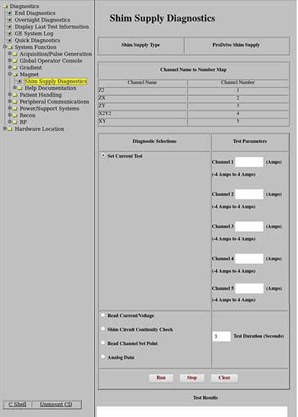
- Select Set Current Test. You can enter the currents in amps in any of the five possible HOS channels. By typing in the current for each channel and then clicking Run, these currents will be applied to the coil. Current entries must remain between the values listed under each channel and less than 12 amps total.Note: Channels used are updated based on the Shim Supply type.Note: Min/max currents will show a different value based on Shim Supply type.
Figure 2. Set Current Test diagnostic selection 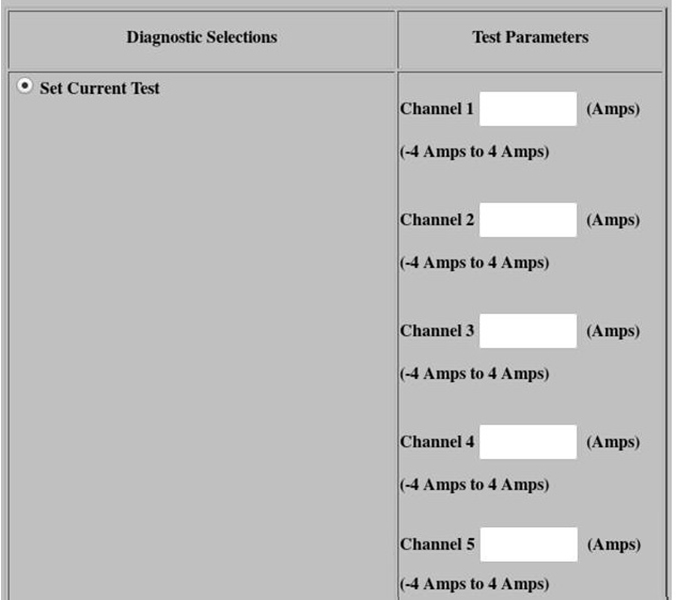
- Check the test results. The measured current test values should approximately match the set values for a given channel.Note: Channels used are updated based on the Shim Supply type.Note: Min/max currents will show a different value based on Shim Supply type.
Figure 3. Set Current Test test results 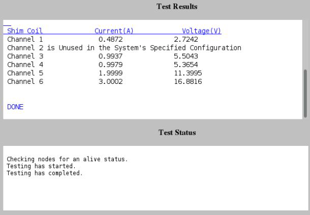
- Check the test results. The measured current test values should approximately match the set values for a given channel.
- Select Read Current/Voltage. This measures and displays the voltage with the set current for a given channel. The actual current in each channel will be written in the Test Results section when this diagnostic is run. This is the amount of current measured by the supply when the diagnostic was run.Note: Channels used are updated based on the Shim Supply type.Note: Min/max currents will show a different value based on Shim Supply type.
Figure 4. Read Current/Voltage test results 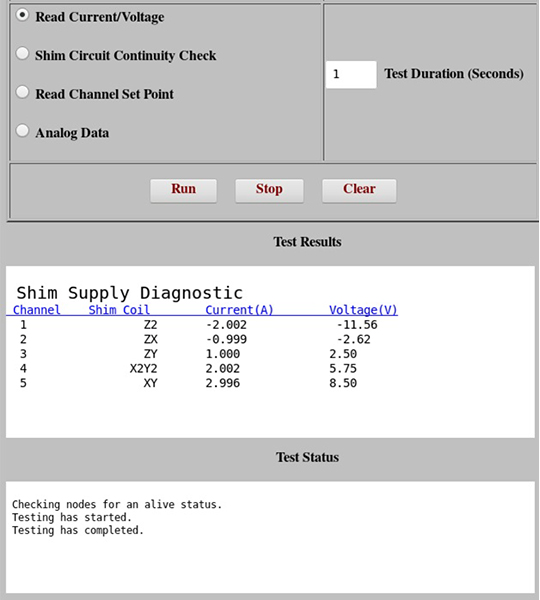
- Select Shim Circuit Continuity Check. This diagnostic applies 0.1 amp to a channel and then reads the measured current on all channels. It then cycles through applying current to each successive channel. The check will indicate if there are any channels that are open or if there are any channels that have a short between coils. In general, it can be used to determine if the HOS circuit is connected and the HOS windings are isolated.Note: Channels used are updated based on the Shim Supply type.Note: Min/max currents will show a different value based on Shim Supply type.
Figure 5. Shim Circuit Continuity Check test results 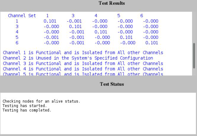
- Select Read Channel Set Point.This measures and displays the present set value of the current in each channel. The diagnostic lists the current setpoints at which the shim supply is operating. It does not display measured data; it only displays the requested setpoints currently in the system. The setpoint is listed in mAmps.Note: Channels used are updated based on the Shim Supply type.Note: Min/max currents will show a different value based on Shim Supply type.
Figure 6. Read Channel Set Point test results 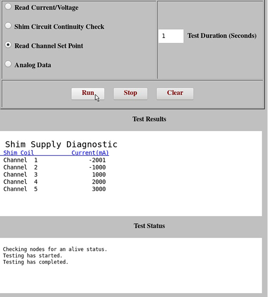
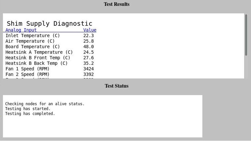
- Select Analog Data. This measures and displays the board level parameters. Analog data provides voltage and temperature measurements that are being monitored by the HOS supply. There are currently no specifications for these values; however, the diagnostic can be used to roughly determine if the power supply is functional.
Figure 7. Analog Data test results